Quantcast
Channel: Copasetic Flow
Viewing all 890 articles
Browse latest View live

Neutrons Used to Probe Dark Matter

$
0
0
From [1]
I'm reading up on a recent expeirment that used a neutron/gravity spectrometer to look for evidence of dark matter and dark energy.  I haven't got to review enough material to say something truly pithy here yet, but I thought I'd point you towards the stuff that's available.  First, here's a discussion of the experiment[1] from Texas A&M's own Dr. Schleich.  He's talked about this kind of thing before, (using neutrons for experiments involving gravity).  In fact, a little more than a year ago he gave a talk here on the KC interferometer and how it measured the acceleration due to gravity as opposed to the gravitational redshift as claimed by the authors[2].  His summary of the current set of experiments comes with the added bonus of a pointer to the open access version of the Physics Review Letters article on the experiment[3].  If you'd like to know how exactly you reflect a neutron from a wall without using coulombic forces which they don't particularly respond to anyway, (the answer has to do with Bragg diffraction), be sure to check out this article on an early test of a neutron interferometer.  Sadly, it's not open access, but again with the advice about local university libraries.

References:

1.  http://physics.aps.org/articles/v7/39

2.  http://copaseticflow.blogspot.com/2013/04/more-on-benchtop-gravitational-redshift.html

3.  http://physics.aps.org/featured-article-pdf/10.1103/PhysRevLett.112.151105

4.  http://www.sciencedirect.com/science/article/pii/0375960174901327


Walkabouts and Lettuce, ahem, Escarole

$
0
0
I've had an undeniable urge to write about well... nothing... this week.  I'm finally giving in.  Indulge me and in a bit, we'll get back to the normally scheduled physics programming.  This all started when I went for a brief walk around campus. First, I hit our local Wells Fargo where they serve free coffee.  As a point of reference, if you open up an account with these guys you can just walk over every morning deposit what you would have spent on coffee and walk out with a cup of coffee.  It's like Starbuck's, but you come out ahead.

Next, I headed back across campus towards the library.  Someone recalled one of my books so I had to hustle and get it back before the end of the week when the overdue fines begin to accumulate.  Walking past the engineering technology building, I noticed that PAID was getting ready for their weekly luncheon.  PAID is the professional association for industrial distribution.  What's industrial distribution you ask?  It's a brilliant new degree they've started offering at Texas A&M.  Let me describe it with an illustration. Let's say you work for a high tech firm as an engineer. You're concerned that eventually your job will be outsourced overseas and frankly your concern is well-founded.  Occasionally, you go to sales meetings where you meet the account manager outside who hops out of his $60,000 BMW wearing his or her $6,000 watch and you head into visit with the customers.  Industrial distribution trains people to be that guy; the $6,000 watch guy!  The guy that got out of the BMW!  Someone's always going to have to sell engineering technology over here even if it winds up being made over here.  The ID department seems to have figured this out, and based on their weekly free lunch is capitalizing on it nicely!


Still heading for the library, the next thing I encountered was a big sign for the upcoming Desserts with Delta Gamma.  The event will  take place at the Delta Gamma house this weekend, and the proceeds will go to help out with various charities related to vision, including the group that supplies seeing-eye dogs.  We're headed over to the event with Jr. and Sam on Saturday afternoon.


Finally, for the last trivial detail of the week, I finally solved the round-edged vs. pointy-edged escarole mystery.  We cooked sausage escarole pasta[1] this week.  It's a recipe from Martha Stewart back in the day when the magazine inserted a page of four pull-out index card sized recipes each month.  The four recipes together constituted an entire meal you could make in two hours.  The cards, obviously intended for their male readers, were about the size of baseball cards and contained precise instructions that allowed no room for error.  The facing page to the cards contained plating suggestions.  The four cards are still featured in the magazine, but sadly they just contain four random recipes now, not a meal, but I digress.  During our stint out on Long Island, we kept finding this stuff labeled as escarole:


You can see from the picture that the same thing happens in TX.  The stuff is pointy leaved and doesn't taste anything like the real deal, but after two years of finding nothing but pointy-leaved escarole, I began to believe that was the only kind there was.  As it turns out, that's very much not the case.  Apparently, there's an unspoken rule that escarole and endive have to be shelved adjacent to one another although there are no requirements that they be labeled.  The pointy-leaved stuff, as it turns out, is endive!  Escarole looks like this:

Notice the nice rounded leaves.  It tastes so much better!

OK, that's out of my system.  Next time: more science!


Vacuum Fittings... Lab Work!!!

$
0
0
I had  lot of ups and downs in the lab yesterday.  The kids, (Jr. aged 3, and Sam aged 1), and I went out ot Bryan Hose and Gasket and picked up our new vacuum hose yesterday.  They had the hose ready and waiting for us and they had the free popcorn machine up and running, so the kids got popcorn.  So, that was cool.  The hose looked a bit small though.

After taking the kids out to visit Blinn College for lunch with their physics professor mom and then returning them to daycare after their mini-adventure, I made it back into the lab.  Sure enough, the hose was too small to fit over our vacuum fitting.  It had seemed like a good idea to cut the old hose behind the fitting to get a better measurement, but I hadn't really thought about the pipe that someone had jammed into one end to permanently expand it so it would fit over the fitting.  The 'jam a pipe in' expansion technique worded fine for red rubber vacuum hosing I'm replacing because its stretchy.  Unfortunately, it won't work at all for our new tubing.   There's a metal coil running through the center of the new tubing to keep it from expanding or collapsing, consequently, the hose is not at all stretchy.  So, that was a bummer.


The net result of all this was we needed new hose, which takes a week or so to get, or new vacuum fittings which I could build in a few hours.  That might sound like it could be a bummer, but it's not.  It means I got to play in the machine shop!!!  I like the theoretical aspects of physics, it's fun to play with the math and especially with the geometry, but I love getting to play around in the lab and the machine shop.  I guess at heart that makes me an experimentalist.  I'm not sure yet, and I'm definitely not ready to decide, but man I love playing with equipment.  To build new fittings, I had to start out with the two blank flanges shown below.  They had to be drilled through to provide a path for air to flow.  Next, a beveled bottom had to be added so the pipe would have something to sit rest on while it was being soldered into the flange.


Using the machine shop lathes, I bored out a hole in each flange, the same size as the inside of the brass tubing that would fit into the new vacuum hose.  Then, I using a boring bar I carved out the bezel that would fit the pipe.


The next step involved playing with the acetylene torch!  I cleaned the pipe and the flange using emery cloth in preparation for the application of soldering flux.  Wikipedia has the best most concise explanation of flux I've seen recently, so here goes:
"In high-temperature metal joining processes (welding, brazing and soldering), the primary purpose of flux is to prevent oxidation of the base and filler materials. Tin-lead solder (e.g.) attaches very well to copper, but poorly to the various oxides of copper, which form quickly at soldering temperatures. Flux is a substance which is nearly inert at room temperature, but which becomes strongly reducing at elevated temperatures, preventing the formation of metal oxides. Additionally, flux allows solder to flow easily on the working piece rather than forming beads as it would otherwise."[1]
Here are the fluxed parts


The next step?  Get the torch to light.  This is a bit simpler than it seems...  You'll see:


The whistling towards the end is my nervous habit when I think things are about to explode.  All was well though.  The issue turned out to be that the gas nozzle was dirty.  After a little cleaning, the torch lit right up.


A few minutes later, (ok, more like half an hour), I had two new fittings.


Scattered Notes on the Parabolic Trajectory Project

$
0
0
The factor of kinetic energy over force in the focus equations got me thinking about work integrals. The work integral also led me to think about the vertex height as a projection back on the y axis. Why? Because work is only done in the direction tangent to the force, which in this case is in the y direction. The calculation of the projection angle was a bit messy, but wound up with a clean if rather obscure result.


The following is neither here nor there, and I suspect will waste more time than it's worth at the moment, so I'm just including it as extra notes to go back to later.

I already know there's a Gudermannian lurking in all of this. The function for the arc length of the parabola contains one. The projection angle consisted of a tanget half angle formula which also leads back to Gudermannians, (seehttps://en.wikipedia.org/wiki/Tangent_half-angle_formula#The_Gudermannian_function).


H-Rays: Mounting the Dewar in the Magnet

$
0
0
I'm deeper into the planning for this summer's experimental search for H-Rays[1].  I've abandoned my previous superconducting magnet designs in favor of a much simpler pre-existing yoke magnet that's sitting out in the hallway.


The pole pieces are in the center of the picture and are retractable using the knobs on the edges of the magnet.  The resulting gap between the pole pieces is where the Dewar will sit,see the picture below:


The Dewar sitting between the pole pieces has created a new theoretical issue.  It's only theoretical for the moment though.  Once we have numbers to go with the theory, we'll find out if our Dewar will wind up looking like this[3][4]:


As +Peter Terren can tell you, rapidly changing magnetic fields like we hope to generate for quenching our superconducting sample will cause Lenz's law eddy currents that create opposing magnetic fields and resulting forces applied to the surfaces that contain the conductors.  What's an aluminum can got to do with a liquid helium Dewar you ask?  The inner jacket of the Dewar is coated with a reflective layer of silver to help with insulation.  If you've got an old coffee Thermos, look inside and you'll see the same thing.  The concern is that the silvered layer will carry induced currents just like the aluminum cans above and create stresses on the glass Dewar.  Our saving grace, hopefully, is that our magnetic field isn't too large and we just won't be able to move it too quickly given the hugely inductive iron magnet pictured above.  That's also one of our problems because we need a quick quench.  Tradeoffs.  Expect to see some back of the envelope calculations here soon.  In the mean time, does anyone know of a completely clear glass Dewar like the one shown below in this classic '60s liquid helium demo movie from Alfred Leitner[4]?


References:
1.  http://copaseticflow.blogspot.com/2013/03/open-science-is-cool-in-concept-but.html

2.  AJP can crushing article, (sadly not open access)
http://scitation.aip.org/content/aapt/journal/ajp/62/1/10.1119/1.17739

3.  Sites addressing can crushing ala magnetic fields
The DeVry IEEE demo site
http://members.tripod.com/extreme_skier/cancrusher/

Tesla DownUnder
http://tesladownunder.com/Links.htm#Tesla Links

(Home of +Richard Green and previously +Jonah Miller), CU can crushing
http://physicslearning.colorado.edu/ldl/demo5K20.65

4.  Liquid helium demo
http://youtu.be/7U4hQ_Y9_Jk?t=3m27s


Can crusher you say?

$
0
0
This is just a quick post to point out that what I thought might be the bane of the H-ray project's existence two days ago my in fact be its saving grace.  Reading more about the can crusher built at the University of Maryland in 1994[1], I came across the following graph.


It appears that the apparatus can generate a greater than 10 kGauss field in under 40 microseconds.  We only require 800 Gauss, so the maximum field seems like a bit of overkill... until you start thinking about the required uniformity of the magnetic field used to make our superconducting sample quench.  Ideally, we'd like to have the entire sample quench at once leaving the spin currents hypothesized by Hirsch nowhere to go.  Hirsch[4] theorizes that the collapsing spin currents are responsible for the Bremsstrahlung radiation, (known as H-rays around here).  By quenching the spin currents everywhere in the superconductor, the number of  H-rays produced should be maximized.

Creating a uniform field of 800 Gauss or so over the entire sample which is a 3.8 cm radius sphere of lead is rather difficult to do using a simple solenoid.  It was this fact that led me to consider using the iron yoke magnet I spoke about in the last post[2].


While the rate of change of magnetic field is distressingly small with this magnet, at least the field is uniform over almost the entire 7.5 cm radius of the pole face, guaranteeing that the whole sample will quench at once,albeit slowly.

This brings us back to the can crusher coil.  It's a rather diminutive little coil consisting of only three turns as designed at U. Maryland.  It does however pack up to a 20 kGauss wallop at its center!  The question is, can it quench the entire volume of the sample at once?  I ran some numbers through our Mathematica[3] solenoid model and came up with the following graph


The y axis is in units of kGauss, the x axis is in units of meters.  The blue curve represents the magnetic field at the center of the solenoid, which is centered at x = 0 and perpendicular to the x axis.  The purple line is the field in kGauss required to quench the lead sample.  The field is high enough throughout the sample!

Of course, this brings back the can crusher issues of the last post in spades, but we can always switch over to an unsilvered fiberglass Dewar and avoid them!

References:
1.  AJP can crushing article, (sadly not open access)
http://scitation.aip.org/content/aapt/journal/ajp/62/1/10.1119/1.17739

2.  Previous post
http://copaseticflow.blogspot.com/2014/05/h-rays-mounting-dewar-in-magnet.html

3.  Mathematica code
https://drive.google.com/file/d/0B30APQ2sxrAYUDlfdTdJLVBBZEU/edit?usp=sharing

4.  Open access version of Hirsch's article on ionizing radiation from superconductors
http://arxiv.org/abs/cond-mat/0508529

Superconductor Background

$
0
0

This video about superconductors is spectacular!  It was sponsored in the 1960s by the National Science Foundation and is narrated by Alfred Leitner of liquid helium movie fame.  The video contains most of the background material necessary for our experimental search for H-rays[1].  It explains and demonstrates the Meissner effect, the critical temperature, pumping on liquid helium to reduce its temperature, and quenching of superconductors via magnetic field.  Parts of it are directed at folks who have had an undergraduate physics class, but as a whole, it's intended for everyone.  The demos are all done in a very large glass Dewar so you can see everything as it happens!
#physics   #physicseducation   #superconductor   #hrays
References
1.  http://copaseticflow.blogspot.com/search/label/hrays


The Superconducting Energy Gap

$
0
0
Watching the Alfred Leitner film on superconductors brought up quite a few things I didn't fully understand about the energy gap of superconductors.

I frequently run into a problem when reading physics,books and articles and especially when watching physics lectures.  If the writer/presenter doesn't outline in broad details where they're headed, a few deleterious, (for me), effects ensue.  First, I'm likely to lose interest altogether.  Second, sine I don't know what the point of the discussion is I usually fail to grasp the few key facts that are embedded within.  This has happened each of the several times I've set out to learn or be taught the details of the energy gap in superconductors.  The same thing almost happened again as I watched Leitner's lecture on the subject, (video excerpt below).  Consequently, I thought it might be handy to provide  a bit of an outline of the key points in the explanation if, like me, you'd rather know where you're headed before you get there.  By the way, if you'd like a very nice article on energy gaps in general, check out this post[1] form +Jonah Miller.


OK,here we go.  First off...
What the experiment and the superconductor energy gap is not about
The tunneling experiment that finds the superconducting energy gap has nothing to do with the superconductor per se.  All metals, even in their normal state exhibit tunneling behavior.  I finally put this together after watching the clip below twice and gawking when I saw the first example of tunneling where Dr. Leitner wrote T > 7.2 K, (picture 1).  In other words, the experiment was done above the superconducting transition temperature of both lead and aluminum, the two metals used in the tunneling junction.


In summary, tunneling is a quantum mechanical effect, but it does not require a superconductor.  Metals in their normal states will do quite nicely, thank you.

As a related ancillary point, the energy gap experiment has nothing to do with Josephson junctions.  These tunneling junctions are very specific to superconductors and function because of very specific superconductor behavior.  Even though the junction configurations look the same, and the names sound the same, the tunneling experiment to determine the superconducting energy gap has nothing to do with Josephson junctions.

And now:
What we're actually watching for
Electrons tunnel from one metal to another through an insulator at near zero temperatures because the number of occupied energy states in the two different metals is different.
As Dr. Leitner points out, almost all metals will exhibit tunneling behavior.  The two metals involved, lead and aluminum, have different Fermi energy levels, (the maximum energy level that electrons are allowed to occupy before they become conducting).  To ensure that all the electrons in the metals are at or below the Fermi energy level, the metal does need to have a temperature near absolute zero.  Hence, the experiment does have to be done at very low temperatures.   Because of quantum mechanical tunneling, the metal with more occupied levels will see the metal, (even through an insulator), with fewer occupied levels and the electrons in the first, more occupied, metal will tunnel to the second, less occupied metal, (picture 2).


This process continues until the occupied levels equalize.  The end result is that the metal, (lead in our case), with fewer levels effectively has its potential raised, (picture 3).


Now, when a voltage is applied between the lead and aluminum contacts, electrons will tunnel from the lead to unoccupied excited energy states in the aluminum, (picture 4).


And Here's Where Superconductors Do Something Different
Here's the punch line.  Because of the energy gap in a superconductor, tunneling will actually stop when the lead sample enters its superconducting state.  There are energy states that are forbidden to electrons in the superconducting lead.  These disallowed states are known as the energy gap of the superconductor.  In the picture below they are the levels between the bold black line and the dotted line on the lead side of the insulator, (picture 5).


In this case, electrons won't flow from the aluminum side to the lead side to equalize the energy levels.  Electrons also won't flow from the lead side to the aluminum side, even when a voltage is applied, until enough voltage is added to the lead side to move the bold line above the level of the bold demarcated energy level on the aluminum side, basically moving the superconducting lead energy gap up and out of the way, (picture 6).


At this point, tunneling occurs again just as it did for the lead sample in the normal state.  Be sure to watch the video below for all the details, the above is just a very widely brushstroked sketch.

Here's one last note of historical interest.  Ivar Giaever[2], a graduate student working at General Electric in 1960 is credited with doing the first experiment that showed the  superconduting energy gap discussed above. This experiment resulted in him sharing the 1973 Nobel prize with Leo Esaki and Brian Josephson.  It was the work of Giaever that inspired the later work of Josephson whom the Josephson junction is named after.


References:
1.  Jonah Miller on energy gaps
http://www.thephysicsmill.com/2013/02/03/im-with-the-valence-band-band-structure-and-the-science-of-conduction/

2.  Ivar Giaever
https://en.wikipedia.org/wiki/Ivar_Giaever

3.  On the battle between Bardeen and Josephson over tunelling
http://www.physics.umd.edu/courses/Phys798I/anlage/AnlageFall12/Josephson%20Physics%20Today%205153075.pdf

4.  permalink to this post
http://copaseticflow.blogspot.com/2014/05/the-superconducting-energy-gap.html


Inaugural Lab Book: Gamma detectors and Fiberglass Dewars!

$
0
0

Lab Book 2014_05_07  Hamilton Carter

Table of the available De Lorenci articles we work with on the rotational QFT project.
Author
Date
Journal
Title
V. A. De Lorenci 1, 2 and N. F. Svaiter 1
1999
Received 1997
Foundations of Physics, Vol . 29, No. 8, 1999
V. A. DE LORENCI and N. F. SVAITER
1999
Received 1998
International Journal of Modern Physics A, Vol. 14, No. 5 (1999) 717–729
V A De Lorenci†, R D M De Paola‡ and N F Svaiter‡
2000
2000 Class. Quantum Grav. 17 4241
V A De Lorenci et al
2001
"Classical and Quantum Gravity Volume 18 Number 1

Dr. DeSilva of UMD passed along the simulation code!!!  It’s written in IDL, so I’ll need to figure out what language that is and how to use it.


Glass bending
I went over to the glass shop and to get the vacuum outlet for the glass Dewar bent into a right angle.  It was awesome to watch!  First the glass blower attached a longer tube to the existing outlet so he'd have a handle.  Then, after heating the tube, he bent it into a complete U before bending it back to 90 degrees  while bending, he blows on the end of the tube to keep a positive pressure inside to keep the tube from kinking or collapsing.   At the end, he detaches the sample tube which leaves the original tube closed.  He heats the end of the original tube and then blows on the opposite end creating a bubble that pops.  The bubble gets broken off using another glass rod over the trash can.  The final step was to put a small flare in the end of the tube using a metal file so that the tube would grip and seal more easily in the red rubber vacuum tubing.  It was an art!


Hose Bracing
I found a brace that will work to relieve stress from the red rubber vacuum hose from affecting the glass joint on the liquid helium Dewar.  Using a drill borrowed from the machine shop, (I found our drill later), I made a small pilot hole for the hose brace. I shielded the Dewar first to make sure it wasn't damaged during drilling.


Once the pilot hole was drilled, the brace was installed and the hose was test fitted.  Everything is working fine and ready to go.


IDL Simulation code
There’s a freeware version of IDL available called GNU Data Language.  IDL stands for interactive data language. 

Scintillator Gamma Ray Detector Testing
I ran the scintillator/PMT detector today and got a few nice traces recorded.  The scintillator is a sodium iodide crystal,(NaI), that produces small flashes of light when gamma rays stop inside it depositing their energy.  These small flashes of light are converted into amplified electricalisgnals by the photomultiplier tube,(PMT).  For the moment, I’m using the oscilloscope to watch the flashes, but ultimately I’ll automate the process using something called an integrating mutli-channel analyzer.  This device automatically keeps track of how many gamma rays of each energy have entered the NaI detector crystal.  The detector is shown below.  The crystal is in the larger portion of the metal tube whose surface is in contact with the lab bench..  The PMT is mounted directly above it in the smaller tube.  The red wire delivers the negative 1700 Volts that biases the PMT and provides the amplification of the light signal.  The black cable connects directly to the oscilloscope so that signals can be viewed.

The negative bias voltage is supplied by an HP high voltage power supply shown here.  Testing was done with a number of bias voltages.  The power supply is shown set to 2000V.

The following two pictures capture the ‘scope settings used.


Video of Cobalt 60 Signals
Each negative pulse is a single gamma ray from the Co 60 source.


Fiberglass Dewar Inspection
We liberated one of the fiberglass Dewars from storage this morning and inspected it.  It looks like it may work with some modification.  There are a few issues though.  First, there’s a fiberglass cup inside that needs to be removed to make way for the superconducting sample holder.  Second, it would be really nice, although not necessary, to be able to access the larger chamber of the Dewar directly to installing a larger superconducting sample.  Right now, access is only available through the 3 1/8” neck opening at the top of the Dewar.  The interior chamber is at least 8” in diameter.
We disassembled the Dewar to determine if there was a way into the larger chamber.  The Dewar has a very simple construction.  There is an inner chamber also made of fiberglass attached to a short neck that is attached to the lid.  Sadly, all attachments are made with glue.  In other words, short of cutting it, we can’t take it apart to access the larger chamber.  The entire inner chamber is surrounded with Mylar super-insulation.  This basically amounts to layer after layer of thin Mylar wrapped around the chamber.  The picture below is the view of the interior of the Dewar through the neck.  The two following pictures are of the exterior of the Dewar.


References:
background to the h-ray experiment if you're new to the game:

http://copaseticflow.blogspot.com/2013/03/open-science-is-cool-in-concept-but.html

Lab Book May 8, 2014 Evaporation of Liquid Helium and YBCO Critical Field

$
0
0


Lab Book 2014_05_08 Hamilton Carter

Summary:  A lot of work was done on the YBCO side of the experiment.  YBCO superconducts at 90 degrees Kelvin or so.  If it can be used, then part of the experiment can be done using liquid nitrogen which is much cheaper than liquid hydrogen.  YBCO produces far fewer x-rays than Pb though, and at a far lower energy.  The fiberglass Dewar I hope to use for the pulsed magnetic field experiments was measured and it compares favorably to the originally proposed Pb sample size.  In the event that the pulsed magnetic coil is placed insside the fiberglass Dewar, it's going to evaporate some of the liquid helium.  Calculations were performed to find out how much and what the pressure build up due to this helium would be.  The pressure number seems suspiciously low and needs to be checked.

I’m catching up on some of the to do items from the last two days.
YBCO Experiments
The plan here would be to look for the critical field using the yoke magnet.  If we can find it, then experiments using liquid nitrogen, which is much cheaper than liquid helium, can be performed using both the yoke magnet and the can crusher coil.


Look into the AJP articles about how other people have added contacts.  Re-read the four point contact strategy.
I found a rather skeletal reference that states silver pain can be used to make contacts on YBCO samples.  The do provide contact information for the supplier, however.  They also have a very nice diagram for the four contact resistivity measurement.   The supplier listed is: Silver paint, cat. No. 16031, Ted Pella, Inc., P.O. Box 492477, Redding, CA 96049


The four point measurement works as follows.  A current is sent through the superconductor using the two outer leads.  As long as the superconductor is in its normal state, (resistive to electrical currents), then there will be a measurable voltage created by the current travelling between the two outer leads.  The two inner leads measure that voltage.


The question that still arises is whether or not we can quench the YBCO superconductor using the iron yoke magnet.  Hirsch’s data table indicates we may be able to, but other tables contradict it.  An article written by Tiernan at the University of Massachusetts indicates that granular YBCO has a much lower critical field than single crystal YBCO.  This is a good sign since we have granular samples from CAN superconductor.  There’s another article about measuring the critical current density that may be useful.  It looks like give a granular sample, Hirsch’s number is believable.  The next step is to look at low energy x-ray samples since YBCO gives much smaller energies than Pb.

As far as what energies can be detected using NaI scintillation, the following data is from 1952.


The available YBCO sample is 14 cm in diameter by 6 mm thick.  Assuming a maximal spherical size of a 3 mm radius gives the following maximum energy and flux as predicted by Hirsch’s formulas.
Maximum energy
(0.3/RCYBCO)*(eMass*c^2)*(1/evToJ)
6339.71 eV
Maximum flux
FluxYBCO[0.3]
136.735  events
The maximum energy is in what Wikipedia calls the hard x-ray region.

Pb and Liquid Helium Work
The Pb sample may be placed into the fiberglass Dewar with the pulsing coil mounted either inside or outside the Dewar.  By mounting the coil outside, we can use a larger Pb sample since we don’t have to account for the radius of the pulsing coil.  DeSilvaused a gap between the coils and the can to be crushed of minimally 0.5 mm.  The coil was constructed with 3 turns of number 10 copper wire.  The wire has a diameter of 2.588 mm.  The down side of mounting the coil outside is that our maximum magnetic field for a given current though the coil will be reduced.
Aside from the larger possible sample size, and the ease of construction, there’s another advantage to mounting the pulser coil outside the Dewar.  Most of the heat created by the coil pulses won’t wind up being deposited in the liquid helium. 
The proposed Pb sample will fit easily into the fiberglass Dewar.  The neck radius on the Dewar is 4.52 cm and the specified sample radius is 3.8 cm.  These dimensions give almost 7 mm of clearance on either side of the sample, which would seem to be enough room to fit the pulsing coil inside the Dewar.


If the coil does go into the Dewar, then there will be concerns about the amount of liquid helium evaporated per coil pulse and how much pressure will build up.  The following is a diagram of the inside of the fiberglass Dewar used for volume calculations.


Assuming only the tail is filled with liquid helium, that gives us the volume of the large chamber and the neck to fill with evaporate liquid helium.  The volume available is calculated below:

Fiberglass Dewar Dimensions (all in inches)ActualScaled
Neck Dia3.56250.8906259.04875cm
Chamber Dia8.06252.01562520.47875cm
Neck Depth12330.48cm
Chamber Depth112.7527.94cm
Tail Depth9.752.437524.765cm
Neck volume1960.117
Chamber volume9202.868
Total volume11162.98

This volume is to be substituted into the ideal gas state equation,


 where n is the number of moles of helium evaporated per pulse, R is the ideal gas constant, 8.314 cm^3 kPa/K mol, T is the temperature of the gas in degrees Kelvin and V is the volume of the gas in cubic centimeters.  The amount of liquid helium that will be evaporated by each pulse, is


 where m is the mass of helium in grams, E is the energy per pulse in Joules, and Q is the latent heat of liquid helium in J/gram. 

All the parameters used and calculated results are shown in the spreadsheet below.
Avagadros number6.02E+23molecues
molar conversion for H4g/moleHe4
Empty volume above liquid helium11162.98cm^3
number of moles5.952380952mol
R8.314cm^3 kPa/K mole
T in Dewar above Li He8K
Specific Heat of Liquid Helium at ~4 K3J/gm.K
Latent Heat of Liquid Helium21J/gm
Density of liquid helium125g/liter
Energy from Pulser500J
Evaporation per pulse23.80952381gm0.19048l
Pressure after pulse0.035465867kPa0.00514psi

Table 1 Evaporation and pressure buildup
The pressure seems a little low.  I may have underestimated the temperature in the Dewar above the liquid helium.

Experimental Setups
SampleQuench SpeedDewarSample SizeDetector
YBCOSlowStyrofoam LiNi replenished16mm x 6 mmFilm
YBCOFastStyrofoam LiNi replenished.  Sample holder reinforced for Lorentz forces.16mm x 6 mmFilm
PbSlowGlass Dewar~1.74 cm radiusNaI
PbFastFiberglass Dewar~3.81 cm radiusNaI


Lab Book 2014_05_09 Experiment Planning, Scotch Tape X-Rays, and Rotational Line Elements

$
0
0

Lab Book 2014_05_09     Hamilton Carter               
Summary
Most of today was spent researching and planning what tasks needed to be done and when.   The only lab work was measuring the more of the dimensions of the fiberglass Dewar and checking on a source for replacement Dewars.  If we’re able to use YBCO, (a type of high temperature superconductor), to prototype the experiment with liquid nitrogen I spent some time determining how the low energy x-rays, (H-rays), could be detected.  One of the possibilities is just to use x-ray film as a type of integrating detector over several runs.  Another possibility s to setup the NaI detector to detect a lower energy spectrum.  The NaI avenue may be blocked to us because of the thickness of the permanent metal window installed around the NaI crystal.

On the theoretical side of things, I spent some time making sure that Franklin’sline element for a rotating frame in special relativity matched with Takeno’s.

Dewar seals
I checked the seal on the fiberglass Dewar that has already been placed into service.


The manufacturer of the seals, Bay Seal  Co. still exists if we need to get replacements.

I found a good looking resource on using NaI as an x-ray detector even at low energies in the single and tens of kV.

Experiment Planning
As it turn out, the proposed Pb sample size will fit in the fiberglass Dewar with the pulsed magnet coil attached.  While it would be nice to confirm quenching of the sample at liquid helium temperatures using the uniform field of the iron yoke magnet, the fiberglass Dewar tail is only 6 3/16” long which will not allow the sample to be placed between the magnets pole pieces.  The magnet coils block the wider Dewar chamber from being lowered between them.
Since we won’t be in position to take delivery of liquid helium until later in the summer, all protyping tests will be run with liquid nitrogen and the YBCO sample.  While the predicted energy and flux are much lower for the YBCO superconductor, the activities will provide an effective and cheaper test bed for our experimental protocols.
The YBCO sample that is to be used is shown below

Hirsch’s predictions depend on the spherical radii.  The largest whole sphere that can be constructed from the material is about 6 mm in radius, consequently, that number is being used as the radius parameter.  If the larger overall diameter of the sample winds up being significant, all the better.
The following is a listing of tasks that need to be performed in roughly the order listed to complete the experiments.

Glass Dewar Leak Detection
This may be put off until later in the project.  The YBCO samples may be cooled in the Dewar, but… Actually, this may still be the best first activity.  Even using only liquid nitrogen, it would be nice to have a vacuum jacketed Dewar.  If we use this Dewar for YBCO quench  characterization, then we’ve tested the vacuum jacket and won’t burn off quite as much liquid nitrogen in the process.  We cannot use the Dewar for YBCO H-ray detection however because the silvered lining will present too great of an attenuation barrier to the very low energy x-rays predicted for this sample size in YBCO, (~10 keV).

Modification of Lab Table for Dewar and Magnet Installation
The bottom shelf of the lab table will need to be removed.  A box has been located to place the glass Dewar in that is currently housed in the table while the work is done.  The bottom shelfof the lab table will be removed and a reinforcing brace between the front two legs will be placed in after the magnet is rolled in below the table.  A new hole will be cut in the table top so that the glass Dewar can be lowered between the poles of the magnet.  The pertinent dimensions showing that the magnet will fit below the table are shown below.

Yoke Magnet Characterization
I first need to leak test, the water cooled power supply for the magnet and setup the cooling attachments for the magnet itself which have been removed.  The interior of the magnet power supply is shown below.  Each of the large black tubes is a water supply line for the cooling manifolds

The magnet will be used to test the quench field of the YBCO sample.  If the sample won’t quench in the 7 kGauss range, then I have to rethink the rest of the procedures.  The yoke magnet will also be used in testing slow quench behavior of the YBCO and for slow quench behavior of Pb if a second smaller Pb sample can be obtained, or the Dewar can be modified to extend its tail.
YBCO Quench Measurement
Using a four point contact arrangement as described in “Handbook of Superconducting Materials, Volume 2” the quenching field of our YBCO sample can be measured assuming it’s below about 7kG or so, (the maximum field the magnet can provide).  The figure below shows the four-point arrangement.  The procedure is describe in yesterday’s lab book entry.

YBCO Sample Preparation
It looks like Electrodag, (a type of sliver paint), can in fact be used to make the four point measurement contacts to the YBCO sample.
NaI Scintillator Characterization in the Dewar
This can be held off until later since it is for use with the Pb sample and the fiberglass Dewar containing liquid helium.  It is however, a relatively easy task, so can be substituted in during any delays.  There’s also the possibility per the Scotch tape article and its associated pyroelectric fusion article in Nature that the NaI crystal can be used to detect the few kV x-rays, (colloquially known as H-rays), from the YBCO. 

The x-rays may not be able to make it through the rather thick window on our NaI detector.  Here's a plot illustrating the point.


Scotch tape video:


Takeno line element in comparison to Franklin’s
I’ve written this down in a LaTex document, so I’ll just cut and paste the results here.  The line element is how distance is measured in a given space.  In Euclidean space, it amounts to the Pythagorean theorm, the sum of the squares of the sides equals the square of the hypotenuse.  For flat space time, roughly the same formula holds but in a hyperbolic geometry.  The upshot of this is that either the time side of the triangle, or the space side winds up with a negative sign.  The choice of which side to make negative is somewhat arbitrary.  In what follows, the mismatches of negative signs that are mentioned are caused by the arbitrary selection of the space vs. time negative side.  In non-Euclidean space, which both Takeno and Franklin are working in, the Pythagorean formula can also have terms with sides multiplied by each other as opposed to themselves.


Lab Book_2014_05_10 Special Relativity, Rotating Frames, and Quantum Mechanics

$
0
0
Lab Book 2014_05_10     Hamilton Carter

Summary
A seemingly simple question about why meagnetic forces act at right angles to their associated field lines led me to derive that the transverse forces on a charged particle moving in a circular path have no gamma terms associated with special relativity.  This seems to tie nicely into why the quantum mechanical number operator predicts no spectrum of Fulling-Unruh radiation from a particle moving in a circular path, but a Fourier decomposition of the wave solution does as shown by Letaw and Pfautsch.  L and P left the lack of spectrum predicted by the number operator as an open question.


Someone asked an interesting question on stackexchange regarding why the Lorentz force from a magnetic field acts at right angles to the direction of the magnetic field.  The simple offhanded answer is that in the fame of the moving particle, the magnetic field transforms into an electric field that is parallel to the direction of the produced force.  Deriving this at length though brought up another interesting point related to the theoretical work that I’m doing.  A byproduct of the derivation is that it points out that there are no special relativistic effects due to forces acting at right angles to the direction of the particle’s moving frame.  Let me say that much more precisely.  If my particle is moving in a circular path, it can be shown that the centripetal force that keeps it in the circular path produces no additional special relativistic effects.
OK, so what does this have to do with my theory research?  I’m looking at one aspect of a problem posed by Letaw and Pfautsch in 1980.  They showed that the spectrum of particles associated with Fulling-Unruh radiation due to circular motion is different than what the quantum mechanical number operator N predicts.  The number operator predicts that ,unlike the case of tangential acceleration which produces a thermal spectrum of particles, in the case of perpendicular acceleration, (circular motion), there should be no spectrum of particles at all.  In their paper, this is left as an unaddressed oddity.
What I figured out today is outlined below.  In all fairness, it might only be a semantic rewording of something that was obvious, but it also might not be.  Here are the points.
1.  Quantum mechanics from the point of view of matter-waves, as developed by DeBroglie, was constructed on top of the special relativistic four momentum vector.
2.  The number operator is constructed on top of quantum mechanics.  See any quantum book for this derivation.  Nieto and Carruthers present a particularly nice derivation for my purposes.
3.  Special relativity produces null results for transverse accelerations, as in circular motion.
4.  It stands to reason that if special relativity doesn’t ‘know about transverse accelerations’, then neither does the number operator, N, constructed on top of it.  Consequently, N never had a chance of producing a non-null spectrum in the problem investigated by Letaw and Pfautsch.

The EM transformation mentioned above follows in pdf.  It utilizes two expressions due to Karapetoff’s oblique angle and hyperbolic treatments of special relativity. 


EM Transformation work in wikiTex
Thanks for asking an interesting question!  One way to think about the answer is using special relativity.  In short, the particle itself sees the magnetic field in, (say the z direction), in our stationary frame transformed into an electric field in the -y direction in its moving frame.  This electric field has the correct magnitude to create a force on the charge equal to the Lorentz force from the magnetic field in our frame.  Just as time and space are actually each part of space-time and transform between each other as the velocity between the moving and laboratory frames change, the electric and magnetic fields are part of the electromagnetic field and transform in a similar manner. 

For a frame, $S^{\prime}$, moving with our charged particle along the x axis with respect to electric, $E$, and magnetic $H$ fields in the laboratory frame, Karapetoff[1][2] gives the following Lorentz transform for the $E'$ and $H'$ fields.

$E_y' = E_y cosh\left(u\right)-H_z sinh\left(u\right)$,

$H_y' = E_y cosh\left(u\right)-H_z sinh\left(u\right)$,

$E_z' = E_z cosh\left(u\right)-H_y sinh\left(u\right)$, and

$H_z' = H_z cosh\left(u\right)-E_y sinh\left(u\right)$,

where $u$ is the rapidity of the frame that moves with the particle. As a matter of reference, u can be expressed as

$v/c = tanh\left(u\right)$,

where v is the speed of the particle in the laboratory frame, but we won't make use of this.

There are a few interesting things to note here.  First, the $E$ and $H$ fields transform via a rotation matrix in a hyperbolic space.  Second, there's an interesting contrast to the Lorentz transform for space-time.  Whereas in space-time only lengths parallel to the direction of motion are changed, when the electromagnetic field is Lorentz transformed, only quantities perpendicular to the direction of motion are changed.

Getting back to the original question, "Why does the magnetic force act at right angles to the magnetic field", let's look at what the moving particle sees in its own frame, S'.  Due to the Lorentz transform shown above, in the $S'$ frame, there is now an electric field in the y direction. 

$E_y' = E_y cosh\left(u\right)-H_z sinh\left(u\right)$,

but  $E_y$ in the laboratory frame is zero so

$E_y' = -H_z sinh\left(u\right)$

There is still an $H$ field in the z direction equal to $H_z cosh\left(u\right)$.  This threw me for a bit, because I was worried about the Lorentz force due to this field.  There is however no need for concern.  Since we're in the frame of the moving charged particle, its relative velocity is zero.  Consequently the magnetic field produces no force in this frame.

Now we'll use the formula

$sinh\left(u\right) = \frac{v}{\sqrt{1-v^2/c^2}} = v\gamma$

to get,

$E_y' = -H_z v\gamma$

We're interested in the force on the particle, $F=qE_y'$, so we write down

$E_y' q = -q H_z v\gamma$

This is starting to look pretty good.  The E field producing a force on the moving charged particle is proportional to the magnetic field times the velocity of the particle.  There's still one problem.  We have a $\gamma$ in the expression which doesn't show up in the Lorentz force law.  Force can also be expressed as $F=ma$.  Since we're working in special relativity, however, we need to express the (transverse in this case) force using relativistic mass so we get $F=\gamma m a$.  This finally gives us

$F = \gamma m a = -q H_z v\gamma$

The $\gamma$'s cancel out to give the correct answer for the magnitude of the force:

$F = -qH_zv$.  In this case, however, the force was created by an electric field in the same direction.

There's one last interesting thing to note here, at least for my purposes.  The force acting in a direction perpendicular to the motion of the charged particle doesn't need to be adjusted for special relativity.  There are no factors of $v/c$ in the final, exact, (as opposed to a low speed approximation), answer.

**References**

1.  Karapetoff, V., "Restricted Theory of Relativity in Terms of Hyperbolic Functions of Rapidities", American Mathematical Monthly, **43**, (1936), 70

2.  Karapetoff, V., "TRANSFORMATION OF ELECTRIC AND MAGNETIC FORCES IN A PLANE WAVE, IN A PLANE NORMAL TO THE DIRECTION OF RELATIVE MOTION OF TWO OBSERVERS", Physical Review **23**, (1924), 239


Lab Book 2014_05_11 Hyperbolic Derivation of the Thomas Precession

$
0
0
Lab Book 2014_05_11     Hamilton Carter
Summary
Most of the day was spent documenting work.  A few new articles inspired more work on the hyperbolic Thomas precession derivation that's been in the hopper for the last few months.

Most of my work today was summarizing the Letaw and Pfautsch vs. the number operator arguments I built yesterday and getting the results out to all the interested parties.

I also found a rather complete reference about the many ways to derive the Thomas precession.  The method that I hope to publish which involves using the Walter methodology to arrive at the Takeno metric was not included!  I should start writing this up, once again, soon.

There are a few other articles regarding Fulling-Unruh radiation in rotating frames that have been added to the reading queue.  The first of these is from Nokic, and the second is from Nelson.  Interestingly, Nokic also published a paper where he opined on the validity of the Rindler quantization.  I’m curious as to what aspects of the first Nokic paper, which is in fact interesting, placed it topically into Physical Review A.  Nelson’s article is quite detailed, and also involves the Thomas precession.  Once again, the hyperbolic derivation I’ve developed isn’t used.

Notes on the new Thomas precession derivation and the associated paper
The introduction to the Thomas precession paper should include the following points:

Ideas for the abstract
There is a quote from the Nelson paper that can be adapted to express the intent of my paper.  Nelson says:
“Historically, accelerated reference frames and the Thomas precession have been studied by approximate methods. 1.2 The coordinates of an accelerated, rotating observer have also been studied by the method of FermiWalker transport.5 In this paper an exact, explicit, nonlinear coordinate transformation that incorporates the Thomas precession and leads to the metric above will be given.”

This sentiment should show up in the abstract of the new paper as something like:
“Traditionally, the Thomas precession has been studied by either numerically or geometrically approximate methods.  We present an exact Lorentz transform matrix that leads directly to the Thomas/Wigner angle for a particle moving in a circular orbit.”

Ideas for the introduction
1.  A general reconstruction of Walter’s arguments in the introduction.  For justification of doing something this way, see Davies et als’ rehash of Letaw and Pfautsch.
2.  Show the different ways this can be viewed including:
2.a.  Laboratory velocity as an angle projecting a constant velocity vector into velocity in time and velocity in space.  The ratio of the two gives the hyperbolic tangent expression usually associated with rapidity.
2.b.  The derivation that shows why acceleration in the laboratory frame can be related to acceleration in the moving frame by gamma cubed.
2.c.  The derivation in the existing Rocketing to Rapidity paper that shows how to derive the gamma squared expression relating dv to dv’.
The body of the paper should perhaps contain the EM derivation performed yesterday that shows the absence of the effects of transverse forces.  This could be followed by why it’s possible to treat the Thomas precession problem as if it were one dimensional, (ala tangential velocity), as opposed to the usual treatment on a two dimensional circle.  This should be followed by the meat of the argument.

Thomas Precession Derivation


Lab Book 2014_05_12 Sample Frame Design and Missing Liquid Nitrogen

$
0
0
Lab Book 2014_05_12     Hamilton Carter

To Do this week in no particular order:
1.       Leak detect the glass and fiberglass Dewars
2.       Check on the availability of the can crusher
3.       Make drawings for sample stage
4.       Check for existing materials that might be used for the sample stage
5.       Find 240 V 3 phase outlet for the magnet power supply
6.       Get the power cord for the magnet supply
7.       Modify lab table
8.       Move magnet
9.       Continue review of the Nikolicpaper concentrating on equations 8 - 11
10.   Continue work on the Thomas precession paper
11.   Check on replacement filters for the leak detector
12.   Move and test NaI detector
13.   Characterize source in Dewar with NaI detector
14.   Magnet test YBCO sample
15.   Find a source for x-ray film and developing

Done Today
Reseated the top and bottom seals on the fiberglass Dewar.  Spent some time brainstorming how to mount the sample in the fiberglass Dewar.


Dewar Design Decision:
The Dewar will not be cut or modified to house a larger sample than can be inserted through the neck.  The sample will be situated in the tail of the Dewar.


Brainstorming sketching.  The coil will be oriented with its axis of rotation directed horizontally.  The coil will be built into a curved fiberglass sample holder that will both reinforce the bottom of the coil and hold the sample.


Dewar Filling
Filled the liquid nitrogen storage Dewar. Empty it weighs 76 pounds and full it weighs in at 173 pounds.  Strangely, I’m unable to figure out how to get the liquid nitrogen to exit the Dewar today.  Opening the liquid or the vent valves produces no results, (haven’t tried both yet).  The pressure gauge reads 0 psi.  The Dewar is still slightly cold to the touch though and feels still feels heavier.


Lab Book 2014_05_13 Leak Detector Work and Checks of Rotating Frames and Special Relativity

$
0
0
Lab Book 2014_05_13     Hamilton Carter               

Summary
After fixing the crusty battery cable in the car this morning, I got to do a little bit of work around the lab before the end of the day.  We met and discussed the special relativity work today as well.  Fermi-Walker transport makes sense as just being the acceleration normal to the tangential velocity that changes the direction of the tangential velocity.

The hose between the auxiliary roughing pump and the leak detector was attached.  The auxiliary pump is used to rough out the volum to be leak detected before using a valve on the leak detector to attach the built in diffusion pump to the volume to attain a much higher vacuum, (in the range of 10E-8 Torrs).

The added hose used the fittings I built a few weeks ago to attach the system.  There’s an intermediate piece that contains an O-ring that fits between the KF fitting on the hose and the pump assembly.
New KF fitting I constructed

O-ring fitting that fits between the two KF fittings

Break-away fitting clamp

Half of clamp enclosing hose and pump fitting with interfacing O-ring

Completely clamped connection

The liquid nitrogen Dewar still had liquid in it, but apparently the lid flange was leaking.  This was not allowing any pressure to build up and so the liquid nitrogen was not exiting the Dewar.  The liquid level was 26 inches as of about 4:30 PM today.  I’ll measure again tomorrow.  We may leak detect a very large liquid helium Dewar along with the glass and fiberglass Dewars.  I need to locate heating tape so we can heat up the Dewar to re-activate the active carbon filter inside.

I worked more on QFT in rotating frames as well.  My original calculations showing that gamma doesn’t participate in the transverse Lorentz force may be incorrect.  I’ve started a new derivation approaching the problem from the direction of four force.  The check and a few notes on Fermi-Walker transport can have been added to the paper positing that the number operator might not be valid for circular motion.


Current pdf version of relativistic work


Lab Book 2014_05_14 YBCO levitation, Glass Dewar Mechanics, and Relativistic Projectile Trajectories

$
0
0

Lab Book 2014_05_14     Hamilton Carter

SummaryTested the larger of the two YBCO superconductors by trying out three different levitation demonstrations.  Ran into a hitch when preparing to vacuum test the glass Dewar.  The glass stopcock valve to the vacuum jacket is stuck shut!  Unbeknownst to me, you can replace glass valves!  Did a bit of theory work looking at hyperbolic trajectories of relativistic particles and how they compare to the trajectories of projectiles with air resistance.

Lab Work:  YBCO Rough Characterization
The YBCO superconductor was levitation tested.  Although it’s not a quantitative measure, it seems to be levitating magnets as well as it ever did.  I ran a series of three demonstrations showing the different types of field cooling/levitation.  In the first experiment, the superconductor was cooled without the magnet present.  Since the sample was very well constructed using a crystal melt method, there aren’t a whole lot of imperfections for magnetic flux to pentetrate into.  The magnet levitates as it would over a type I superconductor that rejects all flux.  In other words, it won’t levitate stably and falls off the opposing field created by the superconductor to one side of the cup or the other.


In the second demo, the superconductor was cooled with the magnet already in place, suspended by a thread a small distance above the sample.  The magnetic flux lines penetrate the superconductor before it enters its superconducting state and are trapped there.  When the superconductor has been cooled and the suspension string loosened, the  magnet levitates.  The superconductor also remembers where the flux lines were located after the magnet is removed.  When the magnet is dropped back down onto the superconductor, its landing is cushioned and it is directed back to its previous levitated location.


In the third case, the magnet is placed directly on the superconductor.  Once again, the lines of magnetic field are frozen in.  This time however, do to the proximity of the magnet to the superconductor, the superconductor won’t let the magnet be pulled apart from it.  Effectively, the superconductor is behaving like a second magnet.


Lab Work: Leak Detector Hookup and Jammed Dewar Stopcock
The leak detector was hooked up to the rubber hose that will evacuate the vacuum jacket on the glass Dewar.

We immediately ran into an issue, however.  The glass stopcock that seals the vacuum jacket was stuck shut.


At the advice of the glass shop we tried to heat the stopcock with a heat gun to loosen it.  The effort was unsuccessful.  I didn’t realize it, but glass stopcocks can actually be replaced.  The glass blower removed our stopcock and will replace it on Friday.


Theory Work: Relativistic Projectiles and their Classically Dragged Counterparts
In addition to having everything you ever wanted to know about classical trajectories of projectiles under the influence of a uniform gravitational field, McAllen includes a section on projectiles with air resistance.  In particular he includes the following figure and formula. 


The right hand side of equation 2 is the innards of an anti-Gudermannian and only needs to be wrapped in a logarithm to be the anti-Gudermannian itself.  Interestingly, the left hand side of the equation is the logarithmic derivative of the particles velocity with respect to its angle with the ground as it moves along its trajectory. The diagram is very reminiscent of the range of a relativistic projectile vs. the angle of launch.  Here’s a graph of the relativistic range as defined by MacColl:


You might notice that this formula also contains an anti-Gudermannian, however in this guise it’s written as the arctanh of a sine function.  Notice that as the factor u in the formula above goes to infinity, it will simply cancel out of the expression. 

Here’s the interesting part of the problem.   The u factor determines how close the projectile is to the speed of light and in fact does approach infinity as the projectile approaches the speed of light.  When the particle hits of the speed of light two things happen.  First, the factor of u cancels out and the range formula is a cosine function times an anti-Gudermannian.  Second, the the optimal launch angle for maximum range is equal to 56.46 degrees.  This is the same angle that will maximize the path length of the trajectory in the classical problem.

We’ve known for a while that the special relativistic effects are all tangential in this problem.  It’s very interesting, yet not unexpected, that the air resistance, (which is also a tangential effect), problem has a  few similarities.

Theory Work: Rotating Frames and Airplanes
Looking into Frenet Serret equations and Fermi-Walker transport.  Leinaas and Korsbaken are using a FS frame and not necessarily a FW frame.  This is mentioned at one point.  Letaw is more careful about that.  Svaiter and Letaw are more concerned about detectors that rotate, (spin).


Elon Musk Pledges Help for the Wardenclyffe Tesla Museum!!!

$
0
0
The Tesla Science Center at Wardenclyffe received a pledge of help from Elon Musk of Tesla Motors fame this week!  The effort begun years ago by the Friends of Science East has inexhaustively progressed year by year to their ultimate goal of turning Nikola Tesla's last laboratory into a bustling science museum and maker space.  You might remember the famous ham radio efforts of folks like myself and a few G+ arteiests like +Diana Eng and +Dashiell Hammutt a few years ago to put the museum effort on the map, so to speak, by transmitting for the first time in over a century from Wardenclyffe and the New Yorker, (Tesla's last home).


Soon after that followed the famous crowd-funding efforts of the Oatmeal's +Matthew Inman put the Tesla Science Center funding over the top and the Wardenclyffe site was purchased, and repairs began in earnest.  The site looks great now, but they need more funding to complete the cleanup and build the museum.  Matthew Inman upped the ante yesterday and asked Elon Musk to help out with the last little bit of funding, all $8 million of it.


Musk's reply was quick and simple for the moment.


It'll be interesting to see where it all goes!  If you'd like to telp out, check out the Tesla Science Center site.

Article 0

$
0
0
Lab Book 2014_05_15     Hamilton Carter

Summary
Almost the entire day was spent finally actually using the leak detector!  The new stopcock was attached to the glass helium Dewar early this morning.  After that, I attended a theory meeting.  After cleaning and vacuum greasing a few fittings we found out that the glass liquid helium Dewar is leak tight!!!  The next step, glass Dewar-wise, will be to modify the table that it sits in so that it can be placed between the poles of the electromagnet.  

I did some more thinking about the relativistic trajectory problem and found some possilbe symmetries in Shahin's expression for the y vs. x.  Both the expressions for hang time and the maximum range equations are interesting. Hang time is interesting because it's actually the same for the relativistic and classical cases.  Range is interesting because the expression involves the vertical component of the projectiles rapidity.


Leak Detecting Procedure
First, attach the system to be evacuated and evacuated to the top of the T-connector.  This allows the system to be vacuumed first by the secondary roughing pump and later by the leak detector’s built-in diffusion pump. 


Make sure that the leak detector to system valve is closed fully in the clockwise direction isolating the system to be detected from the leak detector’s diffusion pump.


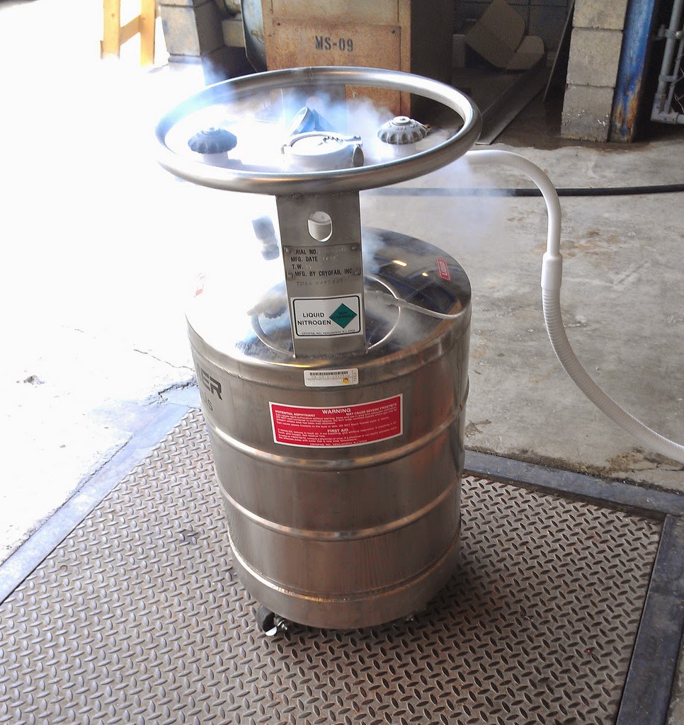
Turn on the leak detector to begin roughing out the diffusion pump.  When the ‘< 10^-2’ indicator light turns on, begin pouring liquid nitrogen into the trap between the diffusion pump and the T joint.  Continue to pour in liquid nitrogen until the trap overflows.  One trap filling should last for up to 10 hours.  Open the gold/yellow auxiliary pump valve by turning it clockwise until it stops.  This will connect the pump to the vessel to be leak detected.


Once the trap is filled, wait 20 to 40 minutes for the roughing and diffusion pump system to completely outgas.  After this, push the filament switch directly below the green indicator lights up.  The filament active light, (the middle light), should light up.  The filament outgasses when it is first turned on causing the vacuum pressure to rise.  You will probably see the vacuum gauge on the right hand side of the control box begin to rise towards the red region.  If the needle makes it into the red region, push the filament switch down to avoid damaging the filament.  The control box should, however, automatically turn off the filament if the gauge reaches the red region.  If necessary, wait another five minutes and then repeat the filament turn on procedure.

Make sure the vacuum gauge for the system to be leaked detected reads below 10^-1 Torr. 


When it does, and when the filament can be left on stably, then slowly begin to open the lead detector to system valve in the counterclockwise direction.  There is a lot of play in the valve, so you will be able to turn it quite a bit without having too large of an effect.  Once again, keep an eye on the vacuum gauge on the right hand side of the control box.  If the needle approaches the red region, begin to close the system valve until the needle once again moves in the green direction.  Wait for the needle to stabilize and then slowly begin to further open the system valve.  Repeat this process until the system valve is completely open.  Once this is done, you can try closing the yellow/gold auxiliary pump valve.  This will usually improve the overall vacuum as the exhaust gasses from the roughing pump are now isolated from the system.

You’re now ready to begin leak detecting with helium.  Point a very low helium flow from a small tube, at various joints in the system, (beginning with the leak detector itself), and listen for the audible leak detection tone to increase in frequency.  If it does increase in frequency, you have found a leak.
To repair a leak, first tighten the leak detector to system valve all the way clockwise.  Then, loosen the small black vacuum release valve located on the side of the copper filter pie entering the T junction.  This will release the vacuum from the system under test.  Perform the necessary repairs, and then repeat the steps listed above from the auxiliary evacuation of the system onwards.  Keep in mind that the filament is still on, so it does not need to be outgassed again.  Make sure however that the system to be leak detected is down to 10^-1 Torr at least before beginning to re-open the leak detector to system valve.

If the system is leak tight, then you can move the sensitivity knob to the next lowest setting as desired.  For Dewars, a leak tight system at the 3*10^-8 setting is sufficient.

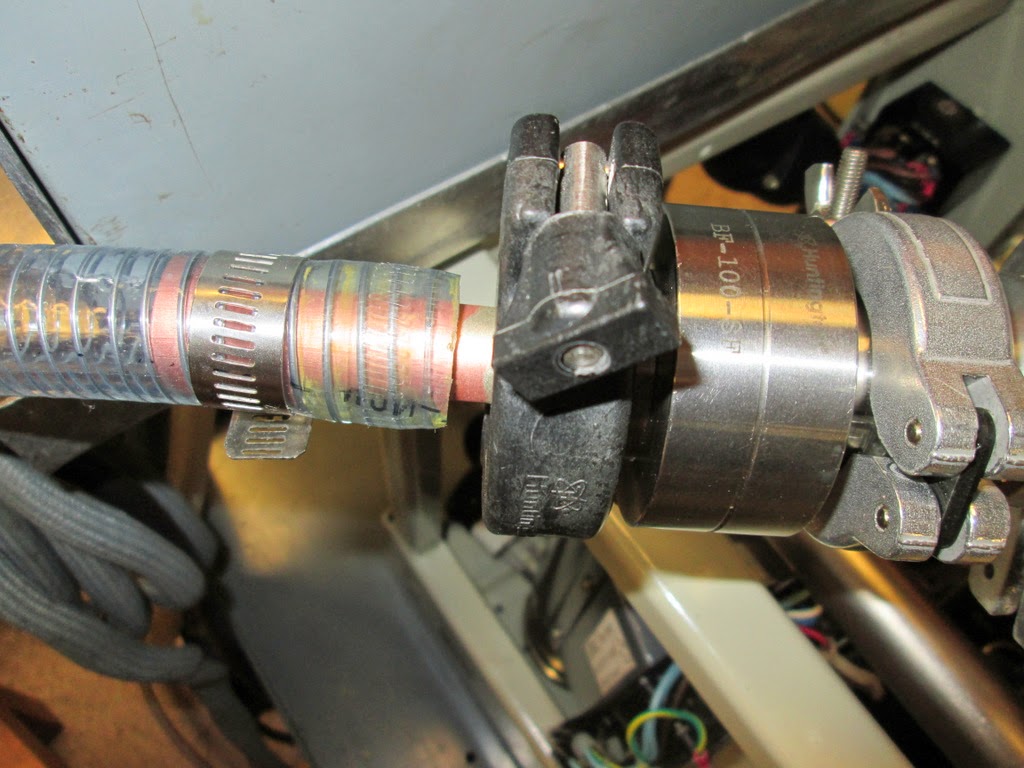
The following picture shows the bracing for the vacuum hose attached to the Dewar.  The bracing turned out to be very necessary.  The metal flex hose contracts when a vacuum is pulled and expands when it is lost.  without the bracing shown, (the bracket on the rubber hose), the ball joint would have been put under undo stress.


Theory Work:  Relativistic Projectiles
The diagram in McAllen elicited a few more thoughts today.  There’s an EJP article with a more useful form of MacColl’srelativistic range expression which is:


The first few terms amount to constants and can be left out of the expression since they will fall away when the derivative is taken to determine the launch angle that maximizes range.  We can then rewrite the expression as:


Compare this to the classical expression


and you begin to wonder if the arctanh term can be linked to the vertical component of velocity in the classical expression.  In fact, it can!  The arctanh term is the expression for the rapidity of the vertical component of the initial velocity.  This begins to beg the question: Can certain classical problems be solved in relativistic frameworks by substituting in the expression for rapidity for velocity?  I need to take a longer look at the expression for the maximum height.
For maximum the height, there is one indication that the vertical component of velocity just doesn’t play in the game.  MacColl points out that the time of flight for both the relativistic and classical particles is the same for the same absolute value of initial momentum and angle of fire, and is


 Keep in mind that MacColl’s mu, is velocity as measured in the lab frame times the relativistic gamma factor also known as the cosh of rapidity.  Also keep in mind that he uses gamma to indicate acceleration, or g, not the usual relativistic gamma factor.

One last qeustion: why are Shahin and MacColl's formulas for the trajectory different?  Is it just notational, or are they actually inequivalent?

Shahin:


Notice the possible symmetry in Shahin's case.  The second expression contains the horizontal component of momentum in the cosh along with the horizontal component of work.  It's scaled by energy over force, a notation which is feels like the distance the work was done over.  The third component contains the orthogonal projection of sinh over the same angle of work divided by horizontal momentum.  This term is scaled by the horizontal component of momentum divided by force however.  Finally, remember that E_o, and p_o c are the horizontal and vertical components of the momentum four vector and that the cosh of rapidity and the sinh of rapidity are the corresponding components of the four velocity vector.

MacColl:


One last note:  Look at the cosine like law in Shahin's velocity and acceleration solutions.

To do:  derive the above equation to determine why the gamma changing as the altitude changes doesn't matter.

Lab Book 2014_05_16 Fiberglass Dewar Leaks and more on Relativistic Projectile Range

$
0
0
Lab Book 2014_05_16     Hamilton Carter

Summary
There's a minor setback.  The fiberglass Dewar has a leak.  On the theory side of things, the relativistic range equation is shown to be proper x velocity times the rapidity of the y component of velocity divided by the acceleration due to gravity which is about what you'd expect it to look like if you first looked at the classical result and then squinted.  Work is being done to determine what, if anything, to make of the result.  Notes and a brief Mathematica file are included.

Leak testing the fiberglass Dewar today.  I’m also looking through the second Tehran paper.


There is a leak at the Teflon joint that is away from the Dewar.  It’s a rather small leak that can’t be detected using the roughing pump gauge.


I've very slightly opened the Dewar valve and begun pumping on the large volume.  After about five minutes, the vacuum was back down to 3 * 10^-1.

It appears that the fiberglass Dewar seals did not reseat. I opened the valve a little more which I expected to improve the vacuum pressure if we didn't have a leak since it would increase the available pumping speed.  The pressure got worse and stayed worse.   The mechanical pump is not pulling below 9*10^-1 after about an hour of pumping.

Theory Work
I showed that Shahin and MacColl’s range equations are equivalent.  The relativistic range equations from Shahin’s paper and my extension, (from yesterday),are


and


I was wrong yesterday.  The factors to the left of the log are constants, but it’s interesting to vary beta.  When it goes to 1, the expression goes to infinity.  There’s one other interesting issue though.  The range expression can also be written as:


Written this way, it’s the horizontal component of proper velocity times the vertical component of rapidity dived by the acceleration of gravity. The product of the speed of light times the veritical component of rapidity divided by g gives a proper time that’s equal to the hang time of the projectile.  There’s a second expression for the vertical hang time agreed upon by both MacColl and Shahin.  The expression is


converting this to proper time, we get


There’s probably a mistake here somewhere, but I’m not seeing it today.

Shahin and MacColl’s range equations were compared[mathematica file] .  They’re quite different notationally, but they are mathematically equivalent.


More raw notes:


Lab Book 2014_05_19 Second Fiberglass Dewar Looks Good!

$
0
0
Lab Book 2014_05_19     Hamilton Carter
Summary
Started work on leak checking a second fiberglass Dewar.  So far, the jacket seems to be holding vacuum well.  The auxiliary roughing pump was pumping more vapor into the system than expected.  Once it was taken out of the circuit, the diffusion pump quickly pulled the jacket back down to a reasonably good vacuum.  No leaks were detected in any of the vacuum junctions, or anywhere on the jacket.

Testing a different fiberglass Dewar.  I wire brushed the old Teflon tape off the vacuum port and and attached the lead detector after putting on new Teflon tape.
Just pumping the hose up to the Dewar, it looked like there might be a leak.  When the rouging pump was taken out of the system after a minute or two, the pressure went back up from about .05 to above .1 rather quickly.  However, after letting the roughing pump work for 28 minutes, when the valve was closed removing the roughing pump, the vacuum held at .05.


The helium leak detector was used to find no leak in the hose or the fitting on the new Dewar.  The Dewar valve was opened and the vacuum gauge moved to > 2.  The roughing pump was left on the volume for several minutes and the vacuum reduced back down to 1.48.


Once the roughing pump was disconnected, the vacuum improved very quickly.  At 17:20, the vacuum read 0.9 on the bottom scale, (all previous readings were on the top logarithmic scale).

17:20
17:20
21:05
21:05

The liquid nitrogen trap was filled at 21:05, and required two and a half Styrofoam cups of liquid nitrogen.  It will be filled again in the early morning.  The trap requires about six cups to fill from room temperature.


Viewing all 890 articles
Browse latest View live