Quantcast
Channel: Copasetic Flow
Viewing all 890 articles
Browse latest View live

Lab Book 2014_05_20 Dewars and Outlets

$
0
0
Lab Book 2014_05_20     Hamilton Carter
Summary
The fiberglass Dewar vacuum held.  The vacuum inlet was plugged to prevent any possible leaks there, and it was stored.  A 480 V three phase outlet for the magnet power supply was located.

4:30 AM Liquid Nitrogen Trap Refilling

Refilled the liquid nitrogen trap that prevents oil vapor from the diffusion pump from migrating opposite the intended vacuum flow into the Dewar’s vacuum jacket.  The liquid nitrogen condenses the oil vapor in the bottom of the small container, (the trap), that it cools.


The trap took two and a half cups of liquid nitrogen to refill.  The vacuum and leak detector readings before and after the fill are shown below.
There was no noticeable improvement in the vacuum and leak readings before and after the Dewar refill.  This makes sense because the Dewar still had liquid nitrogen and was performing its intended function.

Vacuum and leak readings throughout the day
Time
Vacuum
Leak
4:40
4:46
11:09
12:40
15:44


NOTE:  The glass Dewar is at room pressure and can be safely moved.
It’s not possible to check that the vacuum inlet valve doesn’t leak.  To prevent a possible lek even when the valve is shut, a plug was inserted over the inlet valve.


I located a three phase 208 v plug for the magnet power supply.  I need to find a plug that will fit this:


Lab Book 2014_05_21 Cleaning and Planning

$
0
0
Lab Book 2014_05_21     Hamilton Carter
Summary
Reviewed the theory that’s being tested by the experiment.  Looked into digitizing the data with an Arduino and did more cleaning and organizing.


QVT 3001
Looked into how hard it would be to build an Arduino interface to get the detector data out of our QVT 3001.  The QVT 3001 assembles the hits detected by the NaI photomultiplier tube combination into an energy spectrum.


There is an interface that allows external reading and writing of data. The reading interface is summarized in the following two figures.


Since the QVT requires a 16 bit bus, I’m going to need a bigger Arduino.


Hirsch Theory Articles
Reading through Dr. Hirsch’s theory articles again.  They seem to layout the following path:
1.  High temp suerpcodnctors may be explained by the theory of hole superconductivity.
2.  Hole superconductivity fits with BCS but predicts kinetic rather than potential energy lowering for the condentation energy.
3.  Hole superconductivity predicts that negative charges will be expelled from the interior of the superconductor.
4.  The negative charges will create an electric field on the interior of the superconductor.  This might seem counter-intuitive, but is mathematically supported if the charges are moving as spin currents.
5.  Some might object to the spin currents based on Bloch’s theorem, but they are allowed due to spin-orbit intercactions. A reference to this specifically being allowed is Bohm’s paper form 1949.
6.  These spin currents can account for certain not completely explained aspects of superconductivity such as the Meissner effect and the London moment.

Cleaned the A-Frame to be used for lifting the magnet.


Lab Book 2014_05_22 Logistics and the Water Chiller

$
0
0
Lab Book 2014_05_22     Hamilton Carter               

Summary
Worked a little bit on experiment planning today.  Most of the rest of the day was spent in meetings.  What time was left was spent preparing the water circulation system for the magnet power supply and the magnet.

Water Chiller
Specifications
Capacity:  8 gpm at 60 psi maximum pressure

Reservoir volume:  1.67 gallons


Drained the pipes heading into the sink area. Working on replacing the after filter once I track down a filter wrench.  


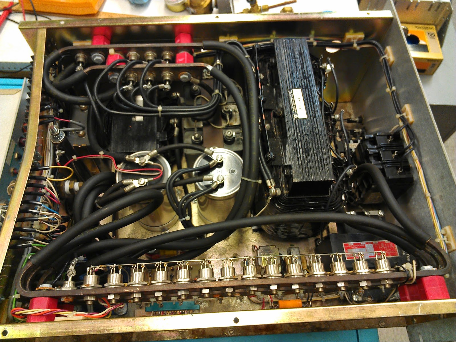
The cooling water will eventually wind up in the magnet power supply shown below.  All the large black tubes carry cooling water.


Magnet Requirements
Cooling:  2 GPM at 40 PSI
Temperature Rise:  20 C average

Magnet Power Supply Requirements
Cooling: 0.5 GPM at 40 PSID nominal
Output: 50 A at 40 V DC

The above specification are to be copied to a central specifications and status page to make them easier to find and track.

Experiment Background Data
Magnetic fields affect the perfromance of photomultiplier tubes like the one used in the scintillation detector.  Background spectrums will be collected for the slow and fast magnets being operated in the same mode they will be operated in the experiment, but with no sample present.  This should allow us to subtract off the effects due to just the magnets.


Photomultiplier Tube History and the Bell Laboratories Record

$
0
0
In our experimental search for H-Rays, we're using a NaI crystal attached to a photomultiplier tube, (PMT),  to detect the predicted x-ray radiation.  While studying up on photomultiplier tubes[1] this week, I came across quite a few interesting historical points.  Among these are:
1.  PMTs were first invented for use in movie theatre projectors to provide the sound tracks.
2.  Equipotential lines were important for design, but computers for the necessary didn't exist yet.  The lines were mapped by stretching thin rubber sheets over wood block models of the electrodes and rolling small balls along the sheets to predict how electrons would move between dynodes in the actual tube.[2] The picture, (picture 1), below shows one of the models being used


3  PMTs were used as radar jammers in world war II.  When fully illuminated,they produce a very natural white noise that can't be distinguished from natural radio static.  The noise was amplified and broadcast to swamp enemy radar.

The article mentioned above is contained in the Bell Laboratories Record. If you're ever looking for an issue, or just want to do some old time tech reading, I found a repository of the back issues[3].

In addition to writing about PMTs, Pierce also wrote an interesting piece on the large balloon satellites that were used for microwave communications testing.  It included a rather spectacular picture of one of the balloons.


G+er's, +Jonah Miller and +Patrick D. Garvey pointed out that the satellites were instrumental in radio astronomy and the discovery of cosmic background radiation.[4]  One of the great things about writing about science on G+ is the incredible audience that frequently adds more information and interesting perspectives!


References:
1.  The Photomultiplier Tube Handbook
http://psec.uchicago.edu/links/Photomultiplier_Handbook.pdf

2.  The article on equipotential analog computers
http://www.americanradiohistory.com/Archive-Bell-Laboratories-Record/30s/Bell-Laboratories-Record-1938-05.pdf

3.  Bell Laboratory Record
http://www.americanradiohistory.com/Bell_Laboratories_Record_Issue_Key.htm

4.  Post with cosmic background comments
https://plus.google.com/108242372478733707643/posts/XTeaDbTNKaP


Lab Book 2014_05_24 Electrical and Cooling Work

$
0
0
Summary
Prep work for magnet power supply testing was done today.  A three phase switch box was wired along with an extension cord to reach from the switch box to the power supply.  The input side of the water chilling system was constructed complete with a flow meter.  Only the output side setup remains.

Background

Hirsch's theory of hole superconductivity proposes a new BCS-compatible model of Cooper pair formation when superconducting materials phase transition from their normal to their superconducting state[1].  One of the experimentally verifiable predictions of his theory is that when a superconductor rapidly transitions, (quenches), back to its normal state, it will emit x-rays, (colloquially referred to here as H-rays because it's Hirsch's theory).

A superconductor can be rapidly transitioned back to its normal state by placing it in a strong magnetic field.  The experiment being performed proposes to look for H-rays emitted by a Pb superconductor when it is quenched by a strong magnetic field.

The lab book entries in this series detail the preparation and execution of this experiment.

Call for Input
If you have any ideas, questions, or comments, they're very welcome!

Checking wire for use with magnet supply

The specs for the wireare as follows:
Product Features
AWG Size:

14
Allowable Ampacity:

15
Amp or Amperage:

15
Cable Type:

Power
Color:

Black
Color Code Chart:

106
Conductor:

Fully Annealed Stranded Bare Copper
Conductor Stranding:

41/30
Construction:

Conductor
Fitting Type:

TB2534K
Insulation:

EPDM
Jacket:

Thermoset CPE
Lbs./M:

208
Length:

Cut To Length
No of Conductors:

4
Nom. Insulation Thickness:

.045 Inches
Nom. O.D.:

.575 Inches
Oil Resistant:

Y
Product Family:

Industrial Cable
Product Type:

Flexible & Portable Cord
Ratings:

UL/CSA
RoHS:

Y
Shielding:

Non-Shielded
Solid/Stranded:

Stranded
Sunlight Resistant:

Y
Temp. Rating:

-40C to 90C
Type:

SOOW
UL:

Y
Voltage:

600V
Water Resistant:

Y
The cable looks like it will just handle the current we want to run through it.

A heavier type P-122 with both a male and female connector is being modified to be fit to the wall mounted switch box. The male connector will be removed and attached to one of the longer E42543 cables. 

The female connector will be left in place and the exposed wires will be attached to the switch box.


The exposed wires on the E42543 cable will be attached to the magnet power supply on the terminal block shown below


The schematic that indicates L1, L2, and L3 are the proper choices is shown below


Checked for shorts between the four leads of the cable and there are none.  The green conductor is attached to the keyed slot of the jack which I’m assuming is the neutral.

I checked the box to make sure all three hot wires were indeed hot, when energized, which they were:


I then turned the breaker off and made sure there was no voltage on the box.


The box was wired to the cord including the green neutral conductor.

Finally, the plug was wired.


Magnet Cooling System
An elbow was placed on the detachable section of the quick-connect for the magnet cooling water so that the water flow meter could be placed in the circuit upright.


References

1.  Hirsch, J. E., “Pair production and ionizing radiation from superconductors”, http://arxiv.org/abs/cond-mat/0508529 


LabBook 2014_05_26 Superconductor Quenching Magnet Chilling Supply and Leak Detector Testing

$
0
0
Superconductor Quenching Magnet Cooling Supply Work
The magnet that will be used to quench the superconductor in our experiment is water cooled.  So is its power supply.  The water chiller that will provide the cooling was checked out and filled.  The plumbing to the supply was constructed and tested.  Two of the water lines required SwageLocks rather than Parker fittings to prevent leaks.
The superconducting sample is to be placed in a liquid helium Dewar during the experiment.  Work is being done to check the status of a second Dewar that can be used as a backup to the first.  At present, the leak detector for this work is not functioning properly.  Some time was spent on debug of the system with no conclusive answers found.

New to the game?  Scroll to the end for background on what this is all about.


Leak Detector Debug
Looking into why the leak detector no longer pulls down to < 10^-2 Torr quickly, (at all?).  Cleaned the liquid nitrogen trap which did have a little bit of pump oil in the bottom.


This didn't seem to help so the next step was to switch the mechanical pump onto the portion of the leak detector system that attaches to the system under test so that the pressure could be read off the system under test pressure valve.  The pump immediately began to evacuate the volume and in under a minute was down to:


After several minutes, the vacuum had reduced to a better, but still not satisfactory value:


The next step will be to switch the pump back to the normal diffusion pump backing position and fill the liquid nitrogen trap with a little bit of liquid nitrogen.  If there really is a trap-vapor problem, this should make things better.
This will have to wait until tomorrow because we’re out of liquid nitrogen and it’s a holiday.

Three Phase Circuit
Did a simple calculation to verify that the voltage measured between one line of the three phase switch box and the neutral will give us what’s expected.  The calculation was done by adding the voltage phasors of two different lines which will be 60 degrees out of phase with each other.  Phasors are vector added.  The process is shown below.


Magnet Supply Cooling Water
The reservoir of the chiller was filled.  Access to the reservoir is on top of the chiller under a Styrofoam cap.  Although it looks small, the reservoir will hold over a gallon of water.  In order to fill the various pipes in the laboratory spanning system, several gallons of water are required to be added to the reservoir.


The return hose on the water chiller interface was extended using a Parker lock fitting and the supply and return hoses were attached to the chiller using Parker fittings.  The pieces of a Parker fitting and the initial assembly are shown below:

As it turns out, no Teflon tape is required for Parker fittings.  The fully assembled hose extension fitting worked like a champ.


The supply and return lines both leaked with Parker fittings.  They were changed out to SwageLock fittings, a different brand with plastic rather than brass ferrules, and the leaks stopped.


The water supply and return system that feed the tubes to the magnet power supply are shown below.  The upright cylinder is the flow meter.  Our current flow rate is one gallon per minute which exceeds our half gallon per minute requirement.


Background
Hirsch's theory of hole superconductivity proposes a new BCS-compatible model of Cooper pair formation when superconducting materials phase transition from their normal to their superconducting state[1].  One of the experimentally verifiable predictions of his theory is that when a superconductor rapidly transitions, (quenches), back to its normal state, it will emit x-rays, (colloquially referred to here as H-rays because it's Hirsch's theory).

A superconductor can be rapidly transitioned back to its normal state by placing it in a strong magnetic field.  The experiment being performed proposes to look for H-rays emitted by a Pb superconductor when it is quenched by a strong magnetic field.

The lab book entries in this series detail the preparation and execution of this experiment.

Call for Input
If you have any ideas, questions, or comments, they're very welcome!

References
1.  Hirsch, J. E., “Pair production and ionizing radiation from superconductors”, http://arxiv.org/abs/cond-mat/0508529 


Lab Book 2014_05_27 Special Relativity, Proper Acceleration, and Magnet Prep

$
0
0
Meetings, Magnets, and Special Relativity
Spent the morning attending a meeting and getting to do just a tiny little bit of special relativity research, regarding proper acceleration in the instantaneously moving rest frame.  The rest of the day was spent debugging, first the liquid nitrogen Dewar, and then the leak detector.  The leak detector is still not up to snuff.  Prep work was done for lifting the magnet that will supply the quenching field for the superconducting samples.

New to these posts?
The hole theory of superconductivity, a BCS compatible modle, predicts that when a superocnductor is brought back to its normal state quickly, it will emit x-rays.  We plan to experimentally verify this or set a new lower limit for its detection.  Scroll to the bottom for more complete information of what this physics experiment is about and what we hope to achieve.

Relativistic range work:
Reviewed and followed Brehme’s derivation of proper acceleration and its meaning.  Proper acceleration is used in the Walterrapidity paper as well as all my rapidity style derivations and winds up in the MacColland Shahinpapers as well.  Here are my notes on Brehme’s interpretation:


For the full scratch-pad LaTex write up of the above notes see https://www.writelatex.com/read/jrvqwgbqbvvj.

Liquid Nitrogen Dewar Refill
An attempt was made to fill the liquid nitrogen Dewar through the lid rather than through the liquid nozzle again.  This resulted in the lid once again not being seated properly and the Dewar not properly developing pressure.  The lid is to be reseated.  Upon reseating, the pressure slowly climbed again and we were able to get liquid nitrogen out of the Dewar.


Magnet Lift and Move
The short bar was placed back in the lifting A-frame.  The A-frame was test fit and does just straddle the magnet.

Ace Bolt and Screw has located the eye bolts we need to lift the magnet!  They’re in Dallas and hopefully will be here by Thursday.  It'll be time for another field trip with the kids!


Background
Hirsch's theory of hole superconductivity proposes a new BCS-compatible model of Cooper pair formation when superconducting materials phase transition from their normal to their superconducting state[1].  One of the experimentally verifiable predictions of his theory is that when a superconductor rapidly transitions, (quenches), back to its normal state, it will emit x-rays, (colloquially referred to here as H-rays because it's Hirsch's theory).

A superconductor can be rapidly transitioned back to its normal state by placing it in a strong magnetic field.  The experiment being performed proposes to look for H-rays emitted by a Pb superconductor when it is quenched by a strong magnetic field.

The lab book entries in this series detail the preparation and execution of this experiment… mostly.  I also have a few theory projects involving special relativity and quantum field theory.  Occasionally, they appear in these pages.

Call for Input
If you have any ideas, questions, or comments, they're very welcome!

References

1.  Hirsch, J. E., “Pair production and ionizing radiation from superconductors”, http://arxiv.org/abs/cond-mat/0508529 

Special Update: Congress to vote on STEM funding for NASA and the NSF today

$
0
0
Congress to vote on STEM funding for NASA and the NSF todayThe House of Representatives is voting on science funding of both NASA and the National Science Foundation, (the guys that pay my paycheck), today.  If you like to read the bill, it can be found at::
http://docs.house.gov/meetings/SY/SY15/20140313/101907/BILLS-113HR4186ih-HR4186FrontiersinInnovationResearchScienceandTechnologyActof2014.pdf

If you'd like to contact your Congressperson to help out, +APS Physics  has setup a handy 'find your congressman' app at 

I called my representiative, Bill Flores and spoke with a very helpful and friendly staffer.  No fuss, no muss.

If you wonder what to say, the APS has ideas for you, read on for a sample email and phone call script:

Sample E-mail

Dear Representative X,

My name is [YOUR NAME], and I am a physicist from [City, State] and a constituent of [Rep. Congressperson]. I work at [Institution] in [City, State]. 

I am writing to ask that you support the strong funding levels for science research at NASA and the National Science Foundation (NSF) in H.R. 4660, the Fiscal Year 2015 Commerce, Justice, Science Appropriations Act and to reject any amendments that are antithetical to science.  We face a difficult moment in history when it is important to both reduce the deficit and debt while also maintaining and growing our economy in the 21st-century.  Economists all agree that, since the end of World War II, science and technology have been responsible for more than half of the United States GDP growth.  In order to compete in knowledge and technology industries which promise future growth, we need to maintain robust federal support for scientific research.

[Personalized story of how NASA/NSF support has made a positive impact in research for you, your colleagues, or others within the Congressional district].

Thank you for your consideration.

Sincerely,

Sample Phone Call

STAFFER: Hello, Congressman X office, how may I help you?
YOU: Hi.  I'd like to speak with the science staffer about the upcoming vote on H.R. 4660.
STAFFER: Let me see if they are in currently.  [You may get to speak with them, be asked if you can deliver your message to the staffer, or be asked to leave a voicemail.]

Upon reaching the science staffer personally or leaving a voicemail.

YOU: Hi, my name is [your name] and I'm a constituent of Congressman X.  I am a physicist and I'm calling to urge to Congressman to support the strong funding levels for science research at NASA and the National Science Foundation in H.R. 4660, the Fiscal Year 2015 Commerce, Justice, Science Appropriations Act and to reject any amendments that are antithetical to science.  We face a difficult moment in history when it is important to both reduce the deficit and debt while also maintaining and growing our economy in the 21st-century.  Economists all agree that, since the end of World War II, science and technology have been responsible for more than half of the United States GDP growth.  In order to compete in knowledge and technology industries which promise future growth, we need to maintain robust federal support for scientific research.


Sincerely
Michael Lubell, 
Director of Public Affairs 
American Physical Society


#physics    #scienceeveryday    #stem  

The Superconductor Hole-Electron Asymmetry of Hirsch

$
0
0
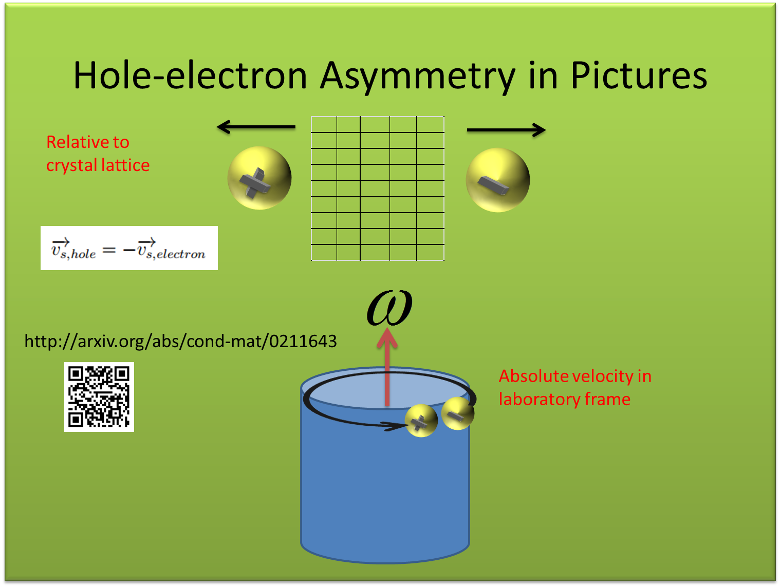
What follows is an explanation of a phrase that Hirsch uses in most of his papers, “hole-electron asymmetry of condensed matter”.  The explanation was adapted from one of Hirsch’s papers[1], that can be found on arxiv as well as Phys. Rev . B.
Hirsch frequently refers to the ‘hole-electron asymmetry of condensed matter’.  In the article entitled “Electron-hole asymmetry and superconductivity”, he provides a nice picture of exactly what he means by this phrase.  I adapted the explanation for a presentation I’ll give soon on the H-ray theory.  The slides follow.  A more complete and texty explanation can be found at the link above.  The text that follows below is the very rough draft of some of the vernacular for the presentation.  For those who are die-hard fans of watching people fumble with practice presentations, I've also posted the first run-through of these slides.  The video is more for my reference than anything else.  You’ve been warned :)


In Hirsch’s papers, he talks a lot about something he calls the hole-electron asymmetry of condensed matter and he has one paper where he actually describes in a pretty nice way what he means by the hole-electron asymmetry of condensed matter.  Normally when you’re doing condensed matter physics you can talk about electrons, (negatively charged particles), or holes.  Holes are taken by al lot of people to mean a lack of an electron so it means a positive charge where an electron would have been and they talk about them fairly symmetrically.  So, for example, they’d say that an electron current moving to the righ in this picture is the same as a hole current moving to the left.  Almost all their equations work out great because when you change the sign of the charge on the charge carrier, you also change the sign of the velocity, and so things like the sign of the current stay the same.  This is what Hirsch describes as symmetry.   You can’t tell l the difference between holes and electrons in a lot of condensed matter physics.

When you get to superconductors, this is where Hirsch points out the hole electron asymmetry.  In superconductors, there are experiments that show that the charge carriers have to be electrons and can’t be holes.  One of them is the London moment.  In that experiment, the physically rotate a superconductor, like our superconducting cylinder here, and a magnetic field is created that points (actually down) into the superconductor if it’s rotating in a counter-clockwise direction.    That field points down because the charge carriers that create the field are electrons, negative charge carriers.  If the charge carriers were holes, they would be positive and the magnetic field would point in the opposite direction.  So, what Hirsch means when he says the hole-electron asymmetry in condensed matter physics is that in superconducting materials, there are experiments where you can tell that the current involved is a current of electrons and not a current of holes moving in the opposite direction.  The reason we believe it’s electrons is that the electrons are moving along with the superconducting cylinder, (lagging just a bit), and when the electrons rotate this way they create a magnetic field that is anti-parallel to the angular velocity vector, which is what we see.


References:
1.  Hirsch, J. E ., ”Electron-hole asymmetry and superconductivity”, Phys. Rev. B, **68**, (2003),

2.  My complete derivation of the London penetration depth from the London field and a few other notes in LaTex.  Thanks to the folks at +writeLaTeX for making everything so easy!


Brillouin Zones, Band Gaps, Bloch Oscillations, the Electron-Hole Asymmetry Theory of Superconductivity

$
0
0
I'm reading through the following in preparation for writing a (hopefully) simplified summary of the electron-hole theory of superconductivity.  For those who would like to follow along, each of the references below i a great resource targeted at different experience levels.

1.   +Jonah Miller's article on band structure as it relates to how materials conduct electric charge[1].  This is a great starting point for the lay-audience.  Jonah is great at explaining physics at any level by the way!  He recently walked Elaine and I through the rudiments of lattice gravity calculations over alcoholic slushies at the +APS Physics April meeting.

Photo Credit +Jonah Miller 


2.  Dr. Likharev's, (of Stony Brook University), Quantum Mechanics I notes relating to the same topic, but from the point of view of Bloch's theorem.  These are targeted at the physics graduate student reader.  His notes show how the unallowed regions in Jonah's article are predicted mathematically; there are no real valued solutions for the quasi-momentum of the charge carrier in the gap.  Dr. Likharev points out some useful derivation starting points, such as using periodic delta functions as a simple model for a crystalline lattice.  He also points out an interesting interpretation of holes.  Mathematically they look like electrons whose effective mass is negative.  This will come in handy later when Hirsch discusses holes un-dressing to become electrons.


3.  Finally, my own article discussing the superconductor band gap video from the '60s.  While I made fun of educational videos like this when I was in school, this on has significantly augmented my understanding of what band structures really mean.  Alfred Leitner rocks!


For those of you who missed the video the first time, here it is again


References:
1.  Jonah Miller on Bandgaps
http://www.thephysicsmill.com/2013/02/03/im-with-the-valence-band-band-structure-and-the-science-of-conduction/

2.  Dr. Likharev's notes
https://drive.google.com/file/d/0B30APQ2sxrAYaXE0MG1FRWxVcDg/edit?usp=sharing

3.  My article regarding the superoncductor energy gap
http://copaseticflow.blogspot.com/search?q=superconductor+band

4.  Alfred Leitner's instructional video about the superconducting energy gap
http://youtu.be/1KuxdKGm3V4


Kinetic Energy Lowering, Covalent bonds,and the Theory of Hole Superconductivity

$
0
0
My review of the material I mentioned yesterday[1] paid off pretty quickly.  Dr. Hirsch is quick to point out that one of the key differences between his 'hole theory of superconductivity'[4] and the more typical explanation of Cooper pair formation is that his theory predicts

kinetic energy lowering after two holes in an energy band pair

as opposed to the usual

potential energy lowering after two electrons pair.

While reading Hirsch's articles, I didn't remember ever coming across kinetic energy lowering pairing before.  It turned out that I had read about it in Dr. Likharev's notes, (see section 2.6, 'Coupled Quantum Wells'), but without an immediate application for the information, I promptly forgot it.

Here are the basics

1.  Crystalline materials, (like superconductors, or semiconductors), in which electrons reside can be very roughly modeled as repeated delta function wells, (picture 1)[2] where the delta functions represent the potentials electrons encounter at each crystal lattice site.  (For an excellent, basic introduction to crystals, see Holden and Morrison's "Crystals and Crystal Growing".[3] This book fascinated me when I was in elementary school and it still does.)


2.  If we look at a pair of wells represented by three of these delta functions, we can create a rough model of how two electrons, (or holes), in neighboring wells might interact with each other.  The important condition of this model, for our discussion, is that the quantum mechanical wave function for each electron must equal zero at the wall of the well, (represented by the delta function).


This condition leads to two possible lowest energy wave functions shown in picture 2[2].  These are labelled S for symmetric and A for anti-symmetric.

3.  The energy of a particle in quantum mechanics is proportional to it's frequency.  Frequency is inversely proportional to wavelength.  So, the anti-symmetric wave function above which has a longer overall wavelength, (spanning two wells instead of one), has a lower kinetic energy than the symmetric one.

4.  Dr. Likharev points out that the anti-symmetric wave function is rough example of a covalent chemical bond between atoms.  Each of a pair of electrons have spread their wave function to encompass two atoms and occupy the same orbit around the two atoms.  The two electrons can occupy the same orbit as long as they have opposite spins.  Dr. Likharev goes on to point out that covalent bonds are stronger than ionic bonds and that they are formed by kinetic energy lowering. (seep picture 3)


This is the same kinteic energy lowering that Hirsch employs in his derivations, albeit in a different application, the pairing of holes at the onset of superconductivity.

Interesting Historical Sidelight
Using the energy stored in the covalent bonds of N2 was once studied as a rocket fuel.  The idea was to break the bonds, store the resulting monatomic nitrogen, and then utilize the kinetic energy expended when the gas explosively recombined to propel a rocket.

References:

1.  Yesterday's post
http://copaseticflow.blogspot.com/2014/06/brillouin-zones-band-gaps-bloch.html

2.  Dr. Likharev's notes
http://goo.gl/SE5QmF

3.  Crystals and Crystal Growing
http://books.google.com/books?id=Sco5b7N4Pb8C&lpg=PP1&dq=crystal&pg=PP1#v=onepage&q=crystal&f=false

4.  Hirsch, J. E., “Pair production and ionizing radiation from superconductors”,
http://arxiv.org/abs/cond-mat/0508529


Background
Hirsch's theory of hole superconductivity proposes a new BCS-compatible model of Cooper pair formation, when superconducting materials phase transition from their normal to their superconducting state.  One of the experimentally verifiable predictions of his theory is that when a superconductor rapidly transitions, (quenches), back to its normal state, it will emit x-rays, (colloquially referred to here as H-rays because it's Hirsch's theory).

A superconductor can be rapidly transitioned back to its normal state by placing it in a strong magnetic field.  The experiment being performed proposes to look for H-rays emitted by a Pb superconductor when it is quenched by a strong magnetic field.

This series of articles chronicles both the experimental lab work and the theory work that’s going into completing the experiment.


Lab Book 2014_06_09 Fixing the Superconducting Quench Yoke Magnet

$
0
0
Scroll to the bottom for background on the experiment.

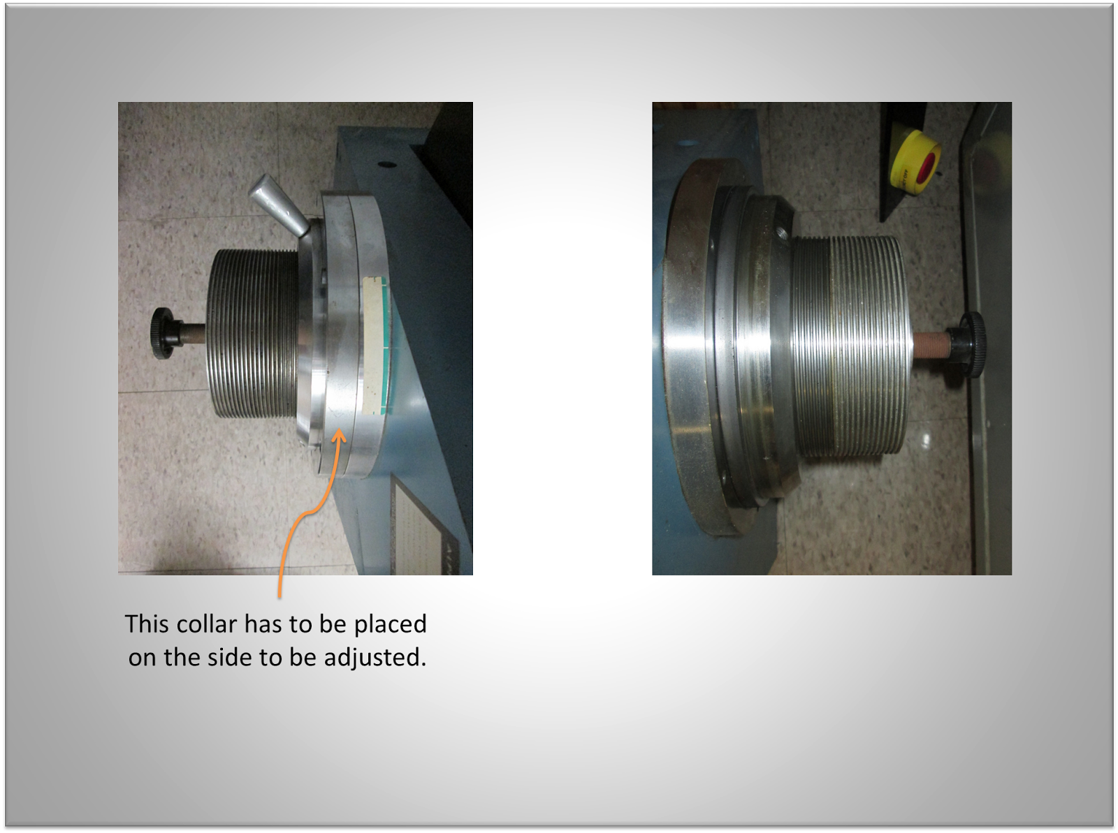
Checked that the pole faces of the yoke magnet retract fully leaving enough room for the glass Dewar.  The poles do retract far enough, but there is a trick to it.  The rotator that advances and retracts the pole piece should have two metal collars associated with it.  On the side I initially tried to adjust, one of the collars was missing and the pole would not move.  When I moved the second collar to that side of the magnet, the pole piece moved after applying a little bit of force


Here's how it works  The collar the handle protudes from is threaded on the inside.  It turns on the threads that are visible and are attached to the pole piece.  If the second collar is in place, then the torque created by the handle is applied to the threads of the pole piece and it slides back and forth through the treads of the handled piece along a small rail at the bottom of the threaded pole.  A screwing motion on the handled collar creates a sliding motion of the pole piece, assuming the second collar is in place.

The magnet with the polished pole faces removed and the poles fully retracted


I subsequently removed the pole faces. I may re-install them if the poles can be retracted far enough to allow the polished pole pieces to be used with a sufficient gap still available.  Detail of pole faces.

Background
Hirsch's theory of hole superconductivity proposes a new BCS-compatible model of Cooper pair formation when superconducting materials phase transition from their normal to their superconducting state[1].  One of the experimentally verifiable predictions of his theory is that when a superconductor rapidly transitions, (quenches), back to its normal state, it will emit x-rays, (colloquially referred to here as H-rays because it's Hirsch's theory).

A superconductor can be rapidly transitioned back to its normal state by placing it in a strong magnetic field.  My experiment will look for H-rays emitted by both a Pb and a YBCO superconductor when it is quenched by a strong magnetic field.
This series of articles chronicles both the experimental lab work and the theory work that’s going into completing the experiment.

The lab book entries in this series detail the preparation and execution of this experiment… mostly.  I also have a few theory projects involving special relativity and quantum field theory.  Occasionally, they appear in these pages.


Call for Input
If you have any ideas, questions, or comments, they're very welcome!

References
1.  Hirsch, J. E., “Pair production and ionizing radiation from superconductors”, http://arxiv.org/abs/cond-mat/0508529 

Physics and Politics H.R. 4660 Science Funding Bill Passed

$
0
0
You may remember a post about a week and a half ago urging everyone to contact their representatives about the upcoming vote on H.R. 4660, the bill that set the spending levels for NASA and the NSF this year among other things.  The bill passed.  My call to my representative Bill Flores apparently didn't hurt, as he voted yes on the bill..  To see the voting record on the bill, check out the record for H.R. 4660.  Interestingly more democrats voted against the bill than republicans.  More interestingly, to me, there are no independents in the House of Representatives at the moment.  One last note of interest: the vote was taken at 1:14 AM.


Getting Back to Basics, Generating the Quenching Magnetic Field

$
0
0
A question from +Yannick Selles inspired today's post which is a rerun of the answer I posted yesterday on G+ with a few more pictures and an additional book reference.  I blame the evil stomach spirits that attacked for the lack of originality :)  Yannick asked how the magnetic fields required to drive the superconducting samples into their normal states, (quenching), for the H-ray experiment, were generated.  Here are the basics

When an electric current travels through a wire, it creates a magnetic field surrounding the wire.


By wrapping a wire into a coil, (a solenoid), the magnetic fields from each turn of wire align to produce a stronger magnetic field.  The black cylinders you see in the picture of the magnet below are solenoids of copper wire.  The black casing carries water to cool off the wire since it also heats up as current is passed through it.


If you want to make an even larger magnetic field, this is where a material like iron comes in.  Iron is made up of magnetic domains that align when they are placed in a magnetic field.  Consequently, when you wrap your coil around iron, not only do you get the field from the coil, you also get the aligned field of all the magnetic domains in the iron.

Here's a picture of the original coil wrap of my cyclotron magnet.  The wrap was scrapped for a more uniform job later, but it gives you a clear picture of the wrapping of the coil onto the iron pole pieces.


The metal you can just barely see in the center of the black wire cylinders is iron.  The metal painted blue is also iron.  Magnetic fields prefer to stay in iron in much the same way electric currents like to stay in wires.  It' the easiest path for them to move in.  We capitalize on this by surrounding the pole pieces with an iron frame that you can see better here:


In this manner, as much of the field as practically possible is focused between the two cylindrical pole pieces.

Entire books have been written on magnetic circuits including this one, (open access on Google Books), by a historical figure I've been researching, Dr.Vladimir Karapetoff of Cornell University.


Background
Hirsch's theory of hole superconductivity proposes a new BCS-compatible model of Cooper pair formation when superconducting materials phase transition from their normal to their superconducting state[1].  One of the experimentally verifiable predictions of his theory is that when a superconductor rapidly transitions, (quenches), back to its normal state, it will emit x-rays, (colloquially referred to here as H-rays because it's Hirsch's theory).

A superconductor can be rapidly transitioned back to its normal state by placing it in a strong magnetic field.  My experiment will look for H-rays emitted by both a Pb and a YBCO superconductor when it is quenched by a strong magnetic field.

This series of articles chronicles both the experimental lab work and the theory work that’s going into completing the experiment.

References
1.  Hirsch, J. E., “Pair production and ionizing radiation from superconductors”, http://arxiv.org/abs/cond-mat/0508529 


Electric Fields from Magnetic Using Special Relativistic Hyperbolic Rotations

$
0
0
I'm trying out +MathJax today.  It's not the most inclusive test in the world, but I figured a good easy runthrough was to publish one of my physics +Stack Exchange answers over here.  A few weeks ago, a user asked why the force on a moving particle due to a magnetic field is perpenicular to both the field and the direciton of motion.  I attempted to answer it using special relativity and Karapetoff's hyperbolic rotation approach to show that to the particle, the magnetic field looks like an electric field at a right angle to its motion.  By the way, everything appears to have worked like a champ, matrices, and all!  Here goes.

One way to think about the answer is using special relativity.  In short, the particle itself sees the magnetic field in, (say the z direction), in our stationary frame transformed into an electric field in the -y direction in its moving frame.  This electric field has the correct magnitude to create a force on the charge equal to the Lorentz force from the magnetic field in our frame.  Just as time and space are actually each part of space-time and transform between each other as the velocity between the moving and laboratory frames change, the electric and magnetic fields are part of the electromagnetic field and transform in a similar manner.

For a frame, $S^{\prime}$, moving with our charged particle along the x axis with respect to electric, $E$, and magnetic $H$ fields in the laboratory frame, Karapetoff[1][2] gives the following Lorentz transform for the $E'$ and $H'$ fields.

$E_y' = E_y cosh\left(u\right)-H_z sinh\left(u\right)$,

$H_y' = H_y cosh\left(u\right)-E_z sinh\left(u\right)$,

$E_z' = E_z cosh\left(u\right)-H_y sinh\left(u\right)$, and

$H_z' = H_z cosh\left(u\right)-E_y sinh\left(u\right)$,

where $u$ is the rapidity of the frame that moves with the particle. As a matter of reference, u can be expressed as

$v/c = tanh\left(u\right)$,

where v is the speed of the particle in the laboratory frame, but we won't make use of this.

There are a few interesting things to note here.  First, the $E$ and $H$ fields transform via a rotation matrix in a hyperbolic space.  Second, there's an interesting contrast to the Lorentz transform for space-time.  Whereas in space-time only lengths parallel to the direction of motion are changed, when the electromagnetic field is Lorentz transformed, only quantities perpendicular to the direction of motion are changed.

Getting back to the original question, "Why does the magnetic force act at right angles to the magnetic field", let's look at what the moving particle sees in its own frame, S'.  Due to the Lorentz transform shown above, in the $S'$ frame, there is now an electric field in the y direction.

$E_y' = E_y cosh\left(u\right)-H_z sinh\left(u\right)$,

but  $E_y$ in the laboratory frame is zero so

$E_y' = -H_z sinh\left(u\right)$

There is still an $H$ field in the z direction equal to $H_z cosh\left(u\right)$.  This threw me for a bit, because I was worried about the Lorentz force due to this field.  There is however no need for concern.  Since we're in the frame of the moving charged particle, its relative velocity is zero.  Consequently the magnetic field produces no force in this frame.

Now we'll use the formula

$sinh\left(u\right) = \frac{v}{\sqrt{1-v^2/c^2}} = v\gamma$

to get,

$E_y' = -H_z v\gamma$

We're interested in the force on the particle, $F=qE_y'$, so we write down

$E_y' q = -q H_z v\gamma$

This is starting to look pretty good.  The E field producing a force on the moving charged particle is proportional to the magnetic field times the velocity of the particle.  There's still one problem.  We have a $\gamma$ in the expression which doesn't show up in the Lorentz force law.  Force can also be expressed as $F=ma$.  Since we're working in special relativity, however, we need to express the (transverse in this case) force using relativistic mass so we get $F=\gamma m a$.  This finally gives us

$F = \gamma m a = -q H_z v\gamma$

The $\gamma$'s cancel out to give the correct answer for the magnitude of the force:

$F = -qH_zv$.  In this case, however, the force was created by an electric field in the same direction.

There's one last interesting thing to note here, at least for my purposes.  The force acting in a direction perpendicular to the motion of the charged particle doesn't need to be adjusted for special relativity.  There are no factors of $v/c$ in the final, exact, (as opposed to a low speed approximation), answer.

Lorentz Force and Four Force
It looks like my above derivation may be incorrect.  Consequently, I'm trying it from a different direction using four-force and the contravarient electromagnetic tensor.  The tensor reads

$F^{\alpha\beta} = \begin{pmatrix}
0 & E_x/c & E_y/c & E_z/c\\
-E_x/c & 0 & B_z & -B_y\\
-E_y/c & -B_z & 0 & B_x\\
-E_z/c & B_y & -B_x & 0
\end{pmatrix}$

The four Lorentz force is defined as the product of the four velocity and the contravarient tensor shown above.  The four-velocity is denoted by
$U_\beta=\gamma\left(-c, u_x, u_y,u_z\right)$

The resulting force tetrad is calculated using $force = qU_\beta F^{\alpha\beta}$

$force_0 = 0 + q\gamma E_x + q\gamma E_y + q\gamma E_z$

$force_x = q\gamma E_x + 0 + q\gamma u_y B_z - q\gamma u_z B_y$

$force_y = q\gamma E_y + -q\gamma u_x B_z + 0 + \gamma u_z B_x$

$force_z = q\gamma E_z + -q\gamma u_x B_y - \gamma u_y B_x + 0$

Where, you'll notice that all the terms on the right hand side are multiplied by a factor of $\gamma$

Each of the velocities on the right hand side is what is known as a proper velocity and corresponds to

$u_a = \frac{dx_a}{d\tau}$,

where $\tau$ is the proper time and is defined as

$\frac{dt}{d\tau} = \gamma = cosh u$

To get back to force in the lab frame, we need to convert the $d\tau$ to a $dt$.  We do this by using $dt = d\tau\gamma$ and multipling both sides of the equation by one over $\gamma$ to arrive at, for example

$force_{xlab} = \frac{dp_x}{dt} = q E_x + 0 + q u_y B_z - q u_z B_y$

However, once again setting the $E$ field to zero, for transverse forces in the lab frame we have $force = m\gamma a_\perp$ so,

$m\gamma a_\perp = q u_y B_z - q u_z B_y$

and

$m a_\perp = \frac{q}{\gamma}u_y B_z - \frac{q}{\gamma}u_z B_y$

but,

$u_y = \gamma v_y$ and $u_z = \gamma v_z$

so,

$m a_\perp = qv_y B_z - qv_z B_y$,

which matches with the original formula.


References

1.  Karapetoff, V., "Restricted Theory of Relativity in Terms of Hyperbolic Functions of Rapidities", American Mathematical Monthly, **43**, (1936), 70

2.  Karapetoff, V., "TRANSFORMATION OF ELECTRIC AND MAGNETIC FORCES IN A PLANE WAVE, IN A PLANE NORMAL TO THE DIRECTION OF RELATIVE MOTION OF TWO OBSERVERS", Physical Review **23**, (1924), 239


Joseph Weber, Gravity Waves, and Robert L. Forward

$
0
0
I got to spend a little time today pursuing one of my hobbies, the history of physics.  I had noticed earlier this week that there were three Trimbles all involved in disparately similar activities, Virginia Trimble, astrophysicist, Charles Trimble, GPS inventor and executive, and George Trimble, NASA deputy director of manned spacecraft during the Apollo missions.  For one of the projects I'm working on I was attempting to find out of the three of them were in any way related, either familially, or by career or professional avenues.  I did find out that Virginia and Charles Trimble attended the California Insittute of Technology during the same time period, but that's about it so far.  Today I got sidetracked by the fact that Virginia Trimble,(picture 1) in addition to being featured in Life Magazine[1], and Twilight Zone promotions[2], was married to Joseph Weber[4].


Joseph Weber is shown in picture 2

Although you can read all about him on Wikipedia, I thought I'd include a few of the intereting bits, (to me anyway), here.  Dr. Weber was the first scientist to build a gravitational wave detector.  In 1968 he began to report on data he was accumulating from the detector and in 1969, he reported the first discover of gravitational waves in Physical Review Letters[3], (open access!).  The results eventually became hotly contested and currently are largely believed to be invalid.  In the process, however, some of the initial ideas for todays gravity wave detectors were worked out.

Weber also presented the first paper detailing the theoretical principles behind masers and lasers[5].  The paper is laid out and communicated an an easily readable fashion with handwritten equations, (picture 3).


Near the beginning of his career, between 1945 and 1948, Dr. Weber headed the Navy's electronic countermeasure design team.

One final note, Dr. Weber had a famous graduate student in Robert L. Forward.  As it turns out, Forward's dissertation involved work on Weber's gravity wave detector.  Forward went on to work at Hughes Research Laboratory where he did further work on a gravity gradient detector.  However, he's probably most widely known as a science fiction author, (picture 4).


References:

1.  Virginia Trimble in Life Magazine
http://books.google.com/books?id=fFUEAAAAMBAJ&lpg=PA95&pg=PA98#v=onepage&f=true

2.  Virginia Trimble in Twilight Zone promotions
http://martingrams.blogspot.com/2012/11/the-twilight-zone-princess-twilight.html

3.  PRL on graviational wave detection (open access)
http://journals.aps.org/prl/abstract/10.1103/PhysRevLett.22.1320

4.  Joseph Weber on Wikipedia
https://en.wikipedia.org/wiki/Joseph_Weber

5.  Laser Maser paper, (sadly not open access)
http://ieeexplore.ieee.org/xpl/articleDetails.jsp?tp=&arnumber=6811068

Mapping Historical Events in Chronological Order: geochrono

$
0
0
In my history of physics research, I've come up with a data visualization application I need that I can't find.  It would be nice to be able to author a list of events and people tied to places and dates and then display them on a map in chronological order.  Using this visualization of information, I'm hoping to find individuals in my research who may have known or worked with each other, or who might have been instrumental in, or related to events in the history of physics.  I did my due diligence and tried to find a free application that already existed, but was unsuccessful.  Here's the open source GitHub for the new application https://github.com/hcarter333/geochrono .  The details follow.

Failing that, I wrote down a very brief description of what I'd like the app to do:

I'm trying to find relationships between individuals that may not be obvious based on their chronological locations. I find myself in need of a tool that will let me map the locations of events and people chronologically, in a KML for example.

and I jotted down a few short requirements


  • Load kml of events and display in table forma
  • Allow entry of data and metadata, (pictures etc…), into table for generation of kml and chronology tour
  • display kml as tour on .js embedded Google Earth map
  • allow user to specify range of tour, which markers to include or exclude, and view screens of the world to watch. Do the last by turning off panning

A few years back, +Shankar Hemmady and I wrote a book, Metric Driven Design Verification about a methodology and processes for bringing a chip design project to fruition successfully.


I've just been out to the DAC conference where this metric driven methodology is being adopted wholesale.  I want to see if I can practice what I preach, so I'm going to try to follow the methodology laid out in the book.  Towards this end, I've setup and open-source project at GitHub, (note:  never open source your chip project, your boss will have a conniption), so others can join in and also so that I can make use of the built-in code revision control system and issue tracking system.  Fun fact:  issue tracking systems used to be called bug tackign systems.  I attended several meetings where it came out that the creative types are generally hurt when their code is called buggy, but don't mind the word 'issue' quite so much, hence, issue tracking systems.  Parts of the methodology, which isn't so different than the extreme programming/refactoring method for software, which I'll be following will be:

Documentation of feature intent along with a testcase that will check that each atomic aspect of the intent has been verified.

Definitions of the roles on the project
I'm hoping to eventually enlist the aid of others on this project, because as much fun as I'm having, man, do I not have the time!  Towards that end, I'm hoping the project will have the following roles/stakeholders who won't all be me.

Coders:  See the above

Web designers:  Because it would be nice if the site were pretty.  This would hopefully encourage more interested folks to use it to two ends.  First, more use means finding issues sooner and fixing them more quickly.  Second, as with all my sites, we'll put some ads up to generate revenue to pay for things like Google server space and coffee.  I think I've also finally figured out a good working model for open source sites that include ads.  If you serve it, then you fork off the module that displays the ads and change the account ID.  To the person paying the server fee go the (very minimal) spoils!  Also, the best served/prettiest version hopefully winds up being the survivor and the rest of us just get to use the tool we wanted in the first place without having to fuss with it!

History Researchers:  Because the quickest way to find out you've implemented the wrong thing is to put the tool in front of someone that needs it.  I of course think I know what I want, but the more perspectives on what would be useful the better.  Also, the sooner they get in the better.


Tracking Metrics
I'll be tracking metrics on everything I can think of for the project.  At first blush, this will be the issue database, the number of testcases passed and failed, and my task list.  The task list will keep me honest.  I only have about a half hour a day to spend on this.  Logging what I do and how long it takes will hopefully keep me in check.

Reusing/Refactoring Code
The code will reuse the guts of three other applications mapmyfriends and findsat and aprsdotfly.  All of these applications were written in kind of the worst style possible.  They're just straight-line scripted with a handfull of functions.  What they do include, however, is code that initiates Google Earth properly,code that sorts through lists of objects to be mapped, and code that plays kml objects as movies on Google Earth.

mapmyfriends

 findsat

aprsdotfly


References:
1.  Verification book
 http://books.google.com/books?id=HgZWmY9TTVsC&lpg=PR1&dq=hamilton%20carter%20metric%20driven%20verification&pg=PR1#v=onepage&q=hamilton%20carter%20metric%20driven%20verification&f=false

2.  findsat
http://copaseticflows.appspot.com/findsat

3.  aprsdotfly
http://copaseticflows.appspot.com/aprsdotfly?tour=ahRzfmNvcGFzZXRpY2Zsb3dzLWhyZHISCxIJQVBSU1RyYWNrGIv0xBUM

4.  geochrono code repository
https://github.com/hcarter333/geochrono


Selling Science with Glossy Pictures and FTL Travel Baby!!!

$
0
0
The Washington Post published pictures of NASA's concept of what a Alcubierre drive spaceship might look like.  A few pundits immediately pointed out that perhaps hyping what amounts to a set of mathematical equations with a spacecraft design might not have been the classiest move on NASA's part.  NASA collaborator Mark Rademaker[1] maintains it was done with the intent of convincing people that STEM is cool, you know, 'for the kids'.  Here's Mark's big, glossy, futuristic design


It's cool and soooo pretty!

Discussion of how STEM should be sold aside, there are now conversations circulating the internet regarding whether or not the ship would violate causality by flying faster than the speed of light.  The answer is, that this might be an issue if the ship actually violated the speed of light by traveling 4.3 light years in 14 days.  As it is though, it doesn't.  Read on:

Travelling Faster than the Speed of Light Without Really Trying, (but not really)
The description in the Washington post article triggers a pretty common misconception:

"If an object reaches a distance x light years away in under x years, then it must be travelling faster than the speed of light."

What the article failed to mention is that the 14 days quoted is in the reference frame of the ship.  The equation for the distance travelled with respect to time in the frame of the ship, (known as proper time), is

$distance = \dfrac{c^2}{a}cosh\left(\dfrac{at}{c}\right)-\dfrac{c^2}{a}$,

where $a$ is the acceleration of the ship and $c$ is the speed of light.

Using this formula, it can be shown that at an acceleration of 188g, (188 times the acceleration due to gravity), the ship could reach alpha centauri in 14 days of ship time.  You might point out that 188 g's would surely smush everyone against the back wall of the ship, but the beauty of the theoretical drive described is that you carry your own gravity well along with you and therefore, you're always in freefall and don't feel the acceleration.

Here's the problem though.  The time that will have elapsed here on Earth will be much, much greater than the 14 days that elapsed on the ship.  The expression for the time elapsed on Earth is

$Earth\ time\ elapsed = \dfrac{c}{a}cosh\left(\dfrac{at}{c}\right)$,

which can be used to show that when the ship reaches alpha centauri, 817 years will have passed here on Earth.

The calculations shown here are nothing new, by the way.  Rindler applied them to the problem of relativistic space travel for the first time in 1960 in a Physical Review article titled "Hyperbolic Motion in Curved Space Time""[2].

References
1.  Mark Rademaker's blog
http://mark-rademaker.blogspot.com/

2.  Rindler, W., "Hyperbolic Motion in Curved Space Time", Phys. Rev. 119 2082-2089 (1960).


I Stand Corrected Regarding the Alcubierre Drive

$
0
0

I jotted down a quick post on the Alcubierre Drive and faster than light travel.  I had assumed that like many FTL misconceptions, the media had been confused by speed measured as proper velocity, (space in the Earth's rest frame divided by time in the spaceships frame), as opposed to lab velocity.  +Jonah Miller quickly pointed out, however, that the claims for the drive were that it could go faster than the speed of light with regard to the laboratory frame, and hence with laboratory velocity.  I found the original paper by Alcubierre on arxiv[1], and...

Jonah's absolutely right!

The paper is amazingly well written and anyone that's had a grad level general relativity class should be able to easily traipse through it.  Alcubierre even shows that causality won't be violated.  I haven't had time to digest the material enough to say why causality isn't violated except with the very unsatisfying statement, "Well, the math works out." Alcubierre was also quick to point out that he felt that with a bit of effort he could come up with an example that would violate causality:

"As a final comment, I will just mention the fact that even though the spacetime described by the metric (8) is globally hyperbolic, and hence contains no closed causal curves, it is probably not very difficult to construct a spacetime that does contain such curves using a similar idea to the one presented here."

OK, so to summarize.  The math explanation and associated formulas I wrote down are correct.  With uniform acceleration and no exotic matter whatsoever, you can travel more than x light years in x proper time years.  In the case of the Alcubierre drive, however, that's not the trick they're playing.  I hope to have more details soon, but in the meantime I'll leave you with this quote from Schild regarding the twin paradox and general relativity.

"A good many physicists believe that this paradox can only be resolved by the general theory of relativity. They find great comfort in this, because they don't know any general relativity and feel that they don't have to worry about the problem until they decide to learn general relativity."

References:
Alcubierre's original warp drive paper
http://arxiv.org/abs/gr-qc/0009013v1


Unintended Benefits of Unit Testing: Documentation for Nothing and Testing for Free

$
0
0
I'm working on the geochrono[1] project a little bit at the time.  I unexpectedly came across a benefit of unit testing I'd forgotten about, documentation by testcase.  One of the first requirements for geochrono is:

The user will be allowed to add events or person chrono-locations by adding markers to a map at the appropriate location.
First implementation 
The user will be required to enter the year, month, and day of the month in three distinct textboxes before clicking on OK. The date will be checked as valid using code available at stackexchange[2].
Testcase: Send bad and good dates to date checker code.
Something like this:


The requirements and testcsases seemed simple enough.  Form a bad date and pass it into the date checking function.  Something like this should have done the trick:


assert.equal(isValidDate(new Date(1980, 100, 150)), false);

You get the idea, pass in a month that doesn't exist, (100), and a day of the month that doesn't exist either, (150).  The problem that cropped up almost immediately was that the Date object is remarkably resilient in creating a date it thinks makes sense even if you hand it garbage.  Consequently, the testcase checking to make sure a 'nonsensical' date was caught by the checker, failed.


There were a number of other combinations that resulted in valid Date objects being created.  This led to the following series of testcases that demonstrated the 'bad dates' that isValidDate will not catch:

QUnit.test( "hello test", function( assert ) {
  assert.ok( 1 == "1", "Passed!" );
  //The following are counter-examples showing how the Date object will
  //wrangle several 'bad' dates into a valid date anyway
  assert.equal(isValidDate(new Date(1980, 12, 15)), true);
  d = new Date();
  d.setFullYear(1980);
  d.setMonth(1);
  d.setDate(33);
  assert.equal(isValidDate(new Date(1980, 100, 150)), true);
  assert.equal(isValidDate(d), true);
  //If you go to this exterme, then the checker will fail
  assert.equal(isValidDate(new Date("This is junk")), false);
  //This is a valid date string
  assert.equal(isValidDate(new Date("November 17, 1989")), true);
  //but is this?
  //Ha!  It's not.  So, the secret to working with this version of
  //isValidDate is to pass in dates as text strings... Hooboy
  assert.equal(isValidDate(new Date("November 35, 1989")), false);
  //alert(d.toString());
});


So, as you can see, the testcases showed that to reuse isValidDate and get the checking behavior I'd like, I'm going to have to submit my dates in the form of a text string.

Of course, the next thing to figure out is how to guarantee that my code always ships in dates in the intended format, but I'll save that for another time.

References:
1.  http://copaseticflow.blogspot.com/2014/06/mapping-historical-events-in.html

2.  http://stackoverflow.com/questions/1353684/detecting-an-invalid-date-date-instance-in-javascript
Viewing all 890 articles
Browse latest View live